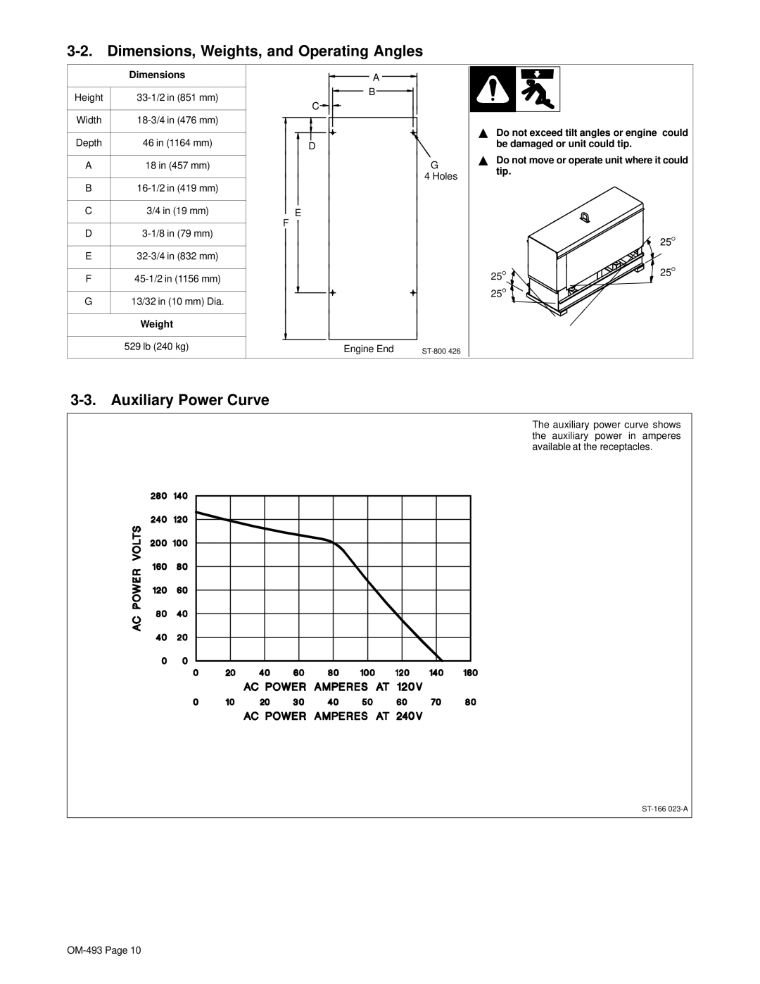
3-2. Dimensions, Weights, and Operating Angles
| Dimensions |
| |
|
|
| |
Height |
| ||
|
|
| |
Width |
| ||
|
|
| |
Depth | 46 in (1164 mm) |
| |
|
|
| |
A | 18 in (457 mm) |
| |
|
|
| |
B |
| ||
|
|
| |
C | 3/4 in (19 mm) |
| |
|
| F | |
D | |||
| |||
|
|
| |
E |
| ||
|
|
| |
F |
| ||
|
|
| |
G | 13/32 in (10 mm) Dia. |
| |
|
|
| |
| Weight |
| |
|
|
| |
| 529 lb (240 kg) |
| |
|
|
|
A
B |
C
D |
G
4 Holes
E |
Engine End |
YDo not exceed tilt angles or engine could be damaged or unit could tip.
YDo not move or operate unit where it could tip.
| 25° |
25° | 25° |
| |
25° |
|
3-3. Auxiliary Power Curve
The auxiliary power curve shows the auxiliary power in amperes available at the receptacles.
