To SCADA Interface
Normal/Pre-lube Drop | O.K. | Lack of | Oil Inlet |
Modes | Pulses | state | Oil | from Reservoir |
Control Circuitry
Preset Selectors & Display
Power
Supply
Line voltage
(115V or 230 V)
or 24V Feed
 Mechanical Stage
Optic
Drop
Detector
Oil Outlet to Shaft
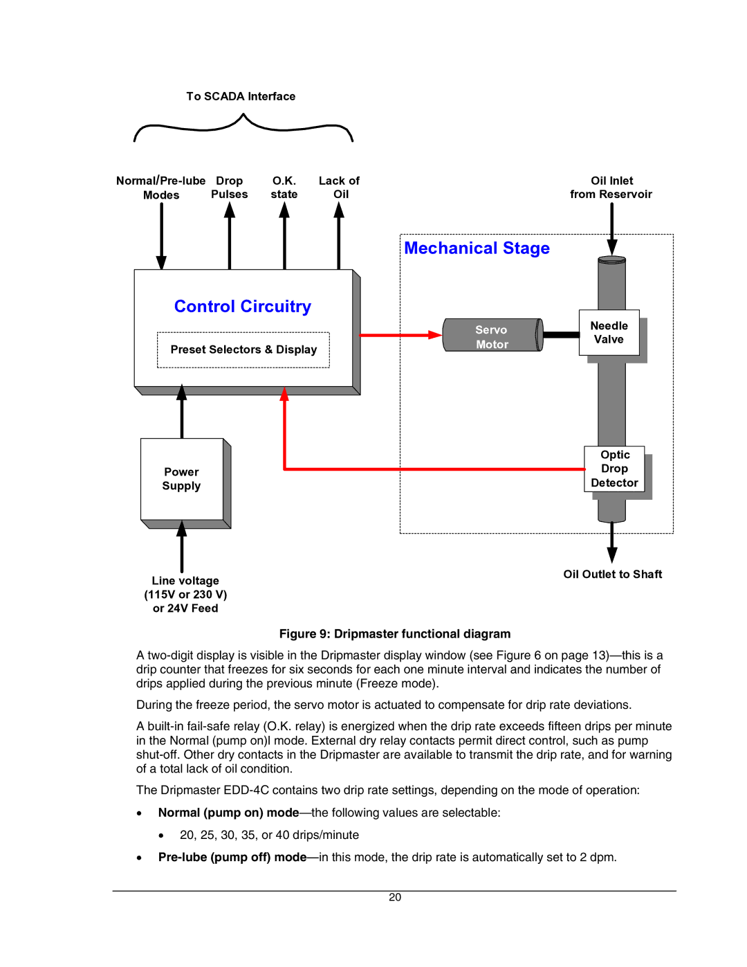
Figure 9: Dripmaster functional diagram
A two-digit display is visible in the Dripmaster display window (see Figure 6 on page 13)—this is a drip counter that freezes for six seconds for each one minute interval and indicates the number of drips applied during the previous minute (Freeze mode).
During the freeze period, the servo motor is actuated to compensate for drip rate deviations.
A built-in fail-safe relay (O.K. relay) is energized when the drip rate exceeds fifteen drips per minute in the Normal (pump on)l mode. External dry relay contacts permit direct control, such as pump shut-off. Other dry contacts in the Dripmaster are available to transmit the drip rate, and for warning of a total lack of oil condition.
The Dripmaster EDD-4C contains two drip rate settings, depending on the mode of operation:
•Normal (pump on) mode—the following values are selectable:
• 20, 25, 30, 35, or 40 drips/minute
•Pre-lube (pump off) mode—in this mode, the drip rate is automatically set to 2 dpm.
20