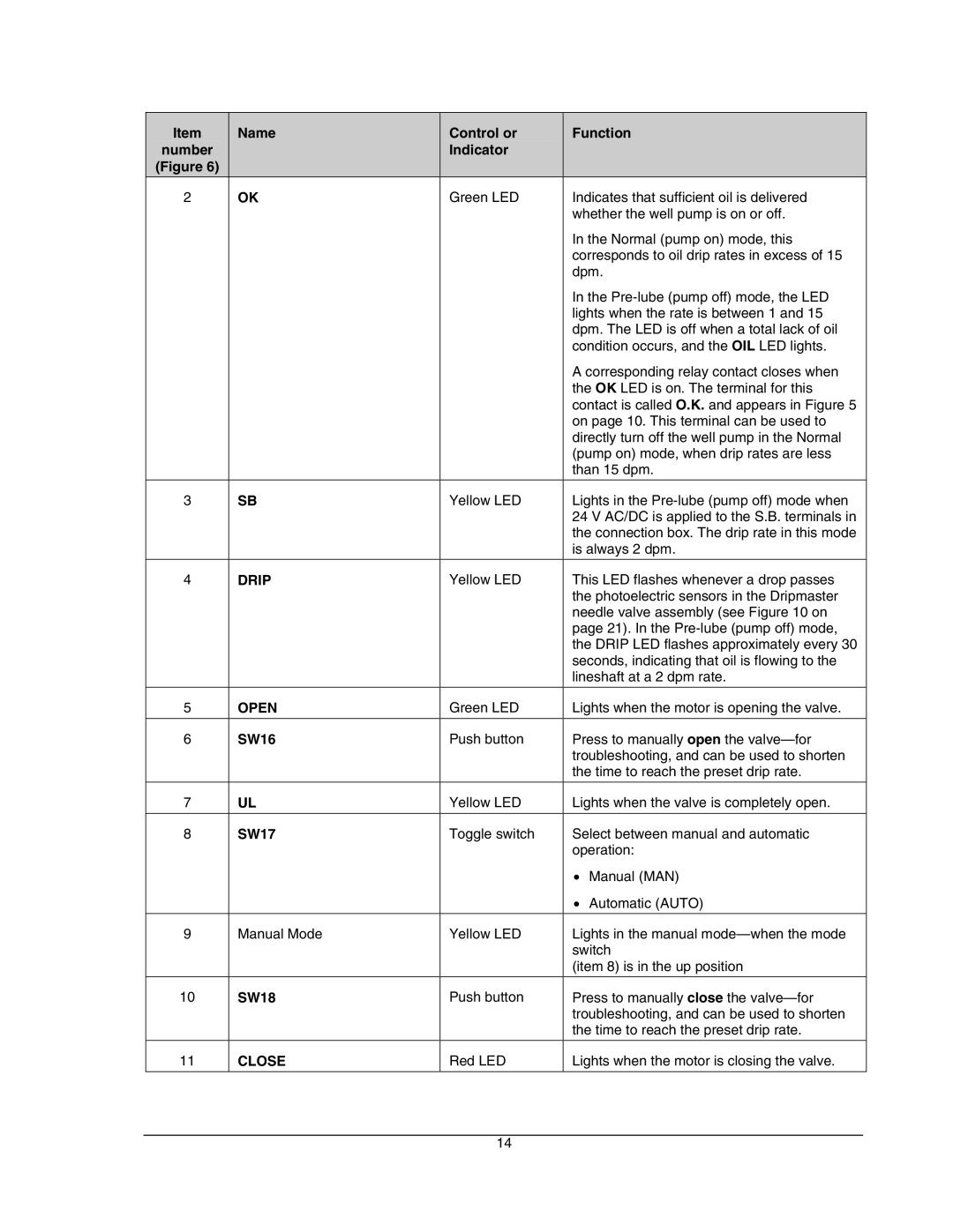
Item | Name | Control or |
number |
| Indicator |
(Figure 6) |
|
|
2 | OK | Green LED |
3 | SB | Yellow LED |
4 | DRIP | Yellow LED |
5 | OPEN | Green LED |
6 | SW16 | Push button |
|
|
|
7 | UL | Yellow LED |
|
|
|
8 | SW17 | Toggle switch |
9 | Manual Mode | Yellow LED |
|
|
|
10 | SW18 | Push button |
|
|
|
11 | CLOSE | Red LED |
Function
Indicates that sufficient oil is delivered whether the well pump is on or off.
In the Normal (pump on) mode, this corresponds to oil drip rates in excess of 15 dpm.
In the
A corresponding relay contact closes when the OK LED is on. The terminal for this contact is called O.K. and appears in Figure 5 on page 10. This terminal can be used to directly turn off the well pump in the Normal (pump on) mode, when drip rates are less than 15 dpm.
Lights in the
This LED flashes whenever a drop passes the photoelectric sensors in the Dripmaster needle valve assembly (see Figure 10 on page 21). In the
Lights when the motor is opening the valve.
Press to manually open the
Lights when the valve is completely open.
Select between manual and automatic operation:
•Manual (MAN)
•Automatic (AUTO)
Lights in the manual
(item 8) is in the up position
Press to manually close the
Lights when the motor is closing the valve.
14
