Caution: | External 24 VAC power source must be |
| isolated from ground. |
|
|
2.Route the power cable through a cable strain relief on the left side of the connection box (Figure 4).
3.Connect the green ground wire to a chassis screw or bolt, preferably using a ring terminal. See Figure 4.
4.Route the control cable through the right cable strain relief (Figure 4).
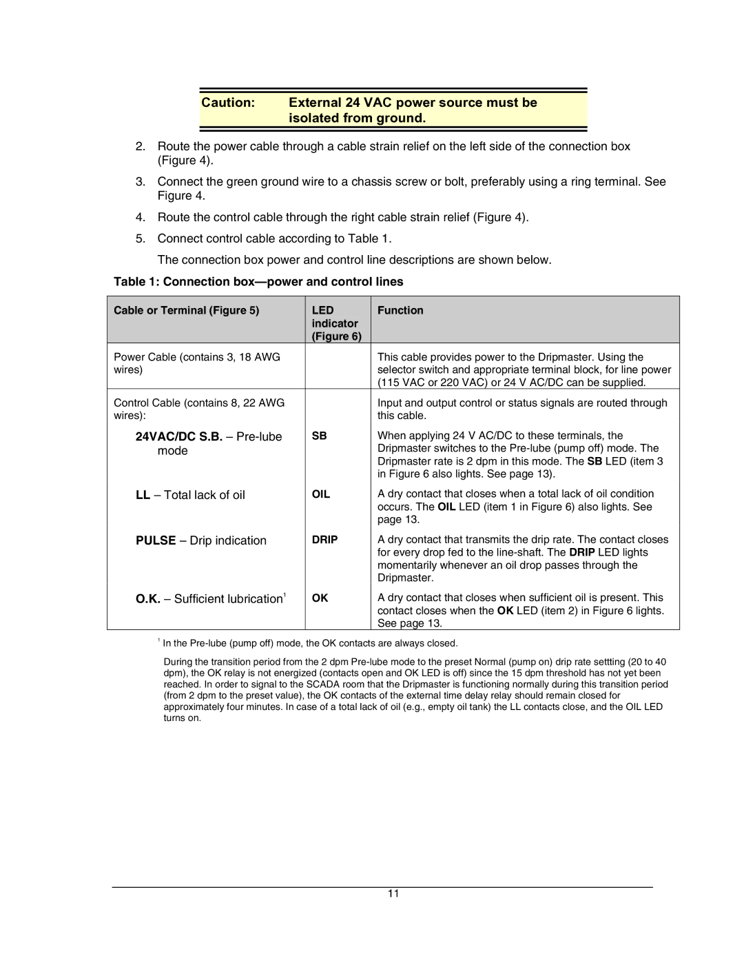
5.Connect control cable according to Table 1.
The connection box power and control line descriptions are shown below.
Table 1: Connection box—power and control lines
Cable or Terminal (Figure 5) | LED | Function |
| indicator |
|
| (Figure 6) |
|
Power Cable (contains 3, 18 AWG |
| This cable provides power to the Dripmaster. Using the |
wires) |
| selector switch and appropriate terminal block, for line power |
|
| (115 VAC or 220 VAC) or 24 V AC/DC can be supplied. |
Control Cable (contains 8, 22 AWG |
| Input and output control or status signals are routed through |
wires): |
| this cable. |
24VAC/DC S.B. – | SB | When applying 24 V AC/DC to these terminals, the |
mode |
| Dripmaster switches to the |
|
| Dripmaster rate is 2 dpm in this mode. The SB LED (item 3 |
|
| in Figure 6 also lights. See page 13). |
LL – Total lack of oil | OIL | A dry contact that closes when a total lack of oil condition |
|
| occurs. The OIL LED (item 1 in Figure 6) also lights. See |
|
| page 13. |
PULSE – Drip indication | DRIP | A dry contact that transmits the drip rate. The contact closes |
|
| for every drop fed to the |
|
| momentarily whenever an oil drop passes through the |
|
| Dripmaster. |
O.K. – Sufficient lubrication1 | OK | A dry contact that closes when sufficient oil is present. This |
|
| contact closes when the OK LED (item 2) in Figure 6 lights. |
|
| See page 13. |
1In the
During the transition period from the 2 dpm
11