R4795A
CHECKOUT
Checkout
![]() CAUTION
CAUTION
Use extreme care while testing the R4795; line voltage can be present on most terminals when the power is On.
CHECKOUT SUMMARY
The following list summarizes the checkout tests re- quired for each type of installation. Instructions for each test are included in this section.
Preliminary Inspection: All installations.
Flame Current Check: All installations.
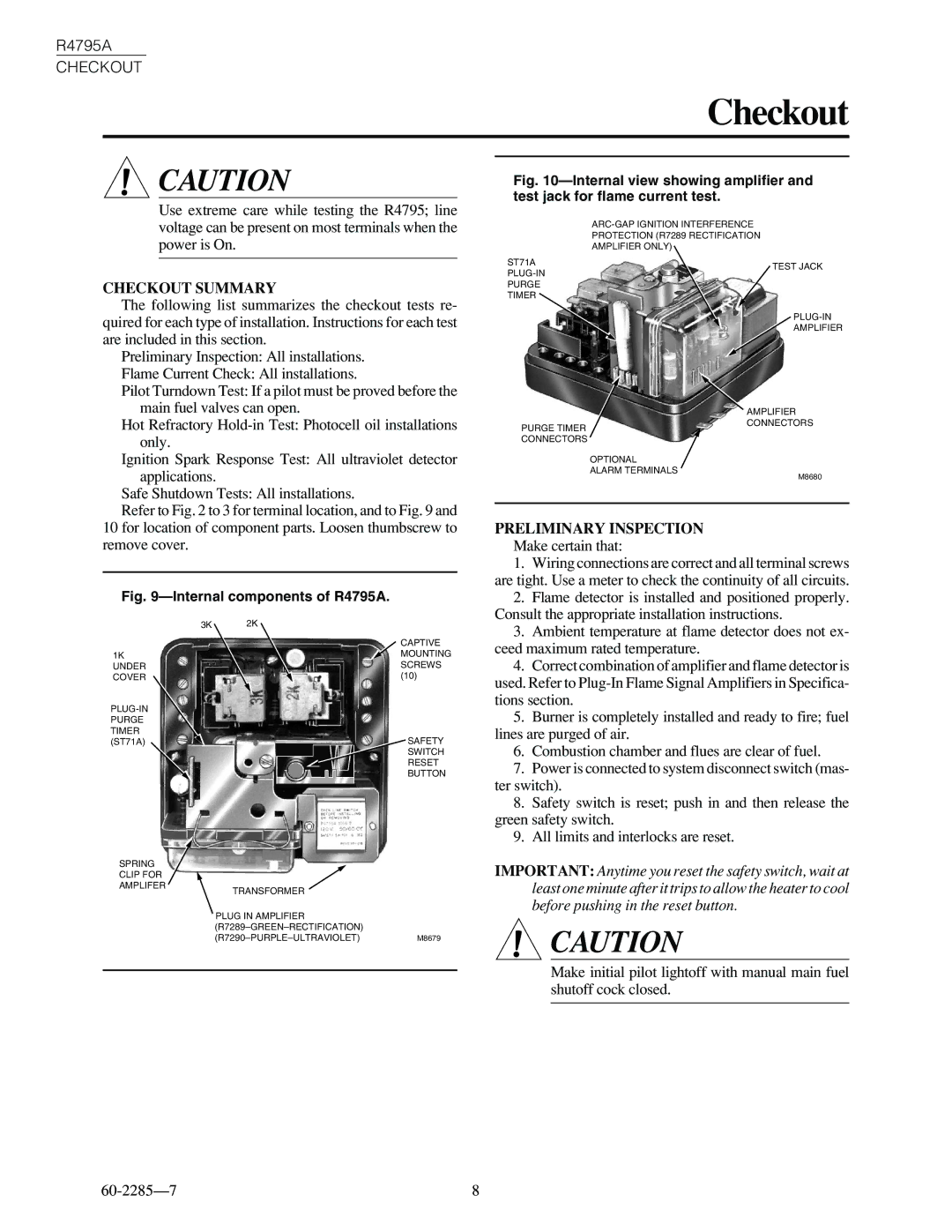
Fig. 10—Internal view showing amplifier and test jack for flame current test.
PROTECTION (R7289 RECTIFICATION
AMPLIFIER ONLY)
ST71A | TEST JACK | |
| ||
PURGE |
| |
TIMER |
| |
| ||
| AMPLIFIER |
Pilot Turndown Test: If a pilot must be proved before the main fuel valves can open.
Hot Refractory
PURGE TIMER CONNECTORS
AMPLIFIER CONNECTORS
Ignition Spark Response Test: All ultraviolet detector applications.
Safe Shutdown Tests: All installations.
Refer to Fig. 2 to 3 for terminal location, and to Fig. 9 and
10 for location of component parts. Loosen thumbscrew to remove cover.
Fig. 9—Internal components of R4795A.
3K | 2K |
| CAPTIVE |
1K | MOUNTING |
UNDER | SCREWS |
COVER | (10) |
OPTIONAL
ALARM TERMINALS
M8680
PRELIMINARY INSPECTION
Make certain that:
1. | Wiring connections are correct and all terminal screws |
are tight. Use a meter to check the continuity of all circuits. | |
2. | Flame detector is installed and positioned properly. |
Consult the appropriate installation instructions. | |
3. | Ambient temperature at flame detector does not ex- |
ceed maximum rated temperature. | |
4. | Correct combination of amplifier and flame detector is |
used. Refer to | |
tions section. | |
SAFETY SWITCH RESET BUTTON
5. | Burner is completely installed and ready to fire; fuel |
lines are purged of air. | |
6. | Combustion chamber and flues are clear of fuel. |
7. | Power is connected to system disconnect switch (mas- |
ter switch). | |
8. | Safety switch is reset; push in and then release the |
green safety switch. | |
9. | All limits and interlocks are reset. |
SPRING
CLIP FOR
AMPLIFER
TRANSFORMER
PLUG IN AMPLIFIER
IMPORTANT: Anytime you reset the safety switch, wait at least one minute after it trips to allow the heater to cool before pushing in the reset button.
![]() CAUTION
CAUTION
Make initial pilot lightoff with manual main fuel shutoff cock closed.
8 |