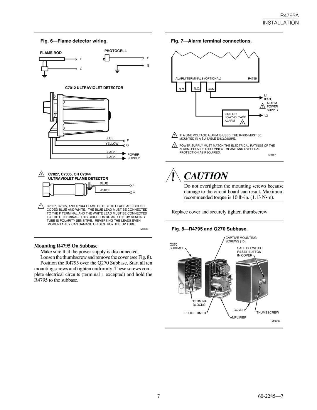
Fig. 6—Flame detector wiring.
R4795A
INSTALLATION
Fig. 7—Alarm terminal connections.
FLAME ROD
PHOTOCELL
| X | F |
|
|
|
|
| X | F |
|
|
|
|
|
| X | G | ||
| X | G |
|
|
|
|
| ||
|
|
|
|
|
|
|
| ||
|
|
|
|
|
|
|
|
|
|
C7012 ULTRAVIOLET DETECTOR
|
|
|
|
|
|
|
|
|
|
|
|
|
|
|
|
|
|
|
|
|
|
|
|
|
|
|
|
|
|
|
|
|
|
|
|
|
|
|
| BLUE | X | F | |
|
|
|
|
|
|
| ||||
|
|
|
|
|
| |||||
|
|
|
|
|
|
| YELLOW | |||
|
|
|
|
|
|
| X | G | ||
|
|
|
|
|
|
| BLACK | |||
|
|
|
|
|
|
|
| POWER | ||
|
|
|
|
|
|
| BLACK |
| ||
|
|
|
|
|
|
|
| SUPPLY | ||
|
|
|
|
|
|
|
|
|
| |
1C7027, C7035, OR C7044 ULTRAVIOLET FLAME DETECTOR
BLUE
X F
WHITE
X G
1C7027, C7035, AND C7044 FLAME DETECTOR LEADS ARE COLOR CODED BLUE AND WHITE. THE BLUE LEAD MUST BE CONNECTED TO THE F TERMINAL AND THE WHITE LEAD MUST BE CONNECTED TO THE G TERMINAL. THIS CIRCUIT IS DC AND THE UV SENSING TUBE IS POLARITY SENSITIVE. REVERSING THE LEADS EVEN MOMENTARILY CAN DAMAGE OR DESTROY THE UV TUBE.
M8686
Mounting R4795 On Subbase
Make sure that the power supply is disconnected. Loosen the thumbscrew and remove the cover (see Fig. 8). Position the R4795 over the Q270 Subbase. Start all ten
mounting screws and tighten uniformly. These screws com- plete electrical circuits (terminal 1 excepted) and hold the R4795 to the subbase.
ALARM TERMINALS (OPTIONAL) | R4795 | ||||||
|
|
|
|
|
|
|
|
N.C. N.O. COM
L1
(HOT)
ALARM
2 POWER SUPPLY
LINE ORL2 LOW VOLTAGE
ALARM
1
1IF A LINE VOLTAGE ALARM IS USED, THE R4795 MUST BE MOUNTED IN A SUITABLE ENCLOSURE.
2POWER SUPPLY MUST MATCH THE ELECTRICAL RATINGS OF THE ALARM. PROVIDE DISCONNECT MEANS AND OVERLOAD PROTECTION AS REQUIRED.
M8687
![]() CAUTION
CAUTION
Do not overtighten the mounting screws because damage to the circuit board can result. Maximum recommended torque is 10
Replace cover and securely tighten thumbscrew.
Fig. 8—R4795 and Q270 Subbase.
CAPTIVE MOUNTING
SCREWS (10)
Q270
SUBBASESAFETY SWITCH RESET BUTTON IN COVER
TERMINAL |
|
BLOCKS |
|
| COVER |
PURGE TIMER | THUMBSCREW |
| AMPLIFIER |
| M8688 |
|
|
7 |