FLAME CURRENT CHECK
The flame current check is the best indicator of proper flame detector application. Perform the check at the time of installation, and at any time service is done on the system, and at least once a month, or more often, while the system is in operation. This prevents shutdowns due to poor flame signal.
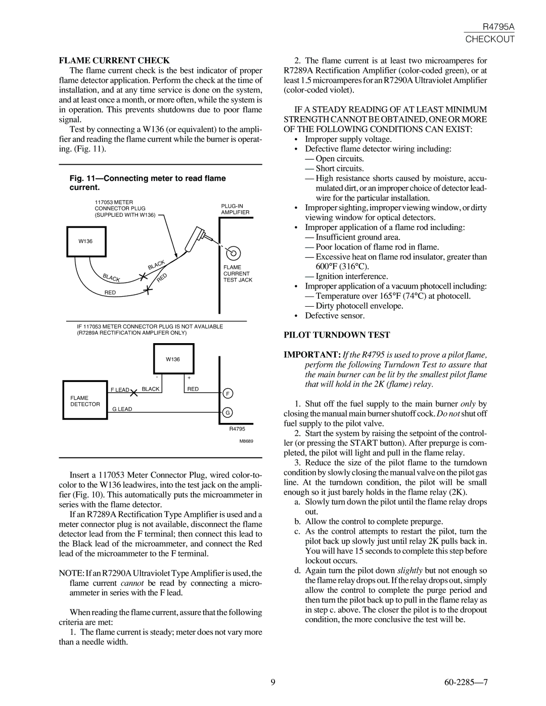
Test by connecting a W136 (or equivalent) to the ampli- fier and reading the flame current while the burner is operat- ing. (Fig. 11).
Fig. 11—Connecting meter to read flame current.
R4795A
CHECKOUT
2.The flame current is at least two microamperes for R7289A Rectification Amplifier
IF A STEADY READING OF AT LEAST MINIMUM STRENGTH CANNOT BE OBTAINED, ONE OR MORE OF THE FOLLOWING CONDITIONS CAN EXIST:
• Improper supply voltage. |
• Defective flame detector wiring including: |
— Open circuits. |
— Short circuits. |
— High resistance shorts caused by moisture, accu- |
mulated dirt, or an improper choice of detector lead- |
wire for the particular installation. |
117053 METER CONNECTOR PLUG (SUPPLIED WITH W136)
W136
| BLACK |
BLACK | RED |
| |
RED |
|
FLAME CURRENT TEST JACK
• Improper sighting, improper viewing window, or dirty |
viewing window for optical detectors. |
• Improper application of a flame rod including: |
— Insufficient ground area. |
— Poor location of flame rod in flame. |
— Excessive heat on flame rod insulator, greater than |
600°F (316°C). |
— Ignition interference. |
• Improper application of a vacuum photocell including: |
— Temperature over 165°F (74°C) at photocell. |
— Dirty photocell envelope. |
• Defective sensor. |
IF 117053 METER CONNECTOR PLUG IS NOT AVALIABLE (R7289A RECTIFICATION AMPLIFER ONLY)
|
| W136 |
| - | + |
F LEAD | BLACK | RED |
FLAME |
| F |
|
| |
DETECTOR |
|
|
G LEAD |
| G |
|
| |
|
| R4795 |
|
| M8689 |
Insert a 117053 Meter Connector Plug, wired
If an R7289A Rectification Type Amplifier is used and a meter connector plug is not available, disconnect the flame detector lead from the F terminal; then connect this lead to the Black lead of the microammeter, and connect the Red lead of the microammeter to the F terminal.
NOTE: If an R7290A Ultraviolet Type Amplifier is used, the flame current cannot be read by connecting a micro- ammeter in series with the F lead.
When reading the flame current, assure that the following criteria are met:
1.The flame current is steady; meter does not vary more than a needle width.
PILOT TURNDOWN TEST
IMPORTANT: If the R4795 is used to prove a pilot flame, perform the following Turndown Test to assure that the main burner can be lit by the smallest pilot flame that will hold in the 2K (flame) relay.
1.Shut off the fuel supply to the main burner only by closing the manual main burner shutoff cock. Do not shut off fuel supply to the pilot valve.
2.Start the system by raising the setpoint of the control- ler (or pressing the START button). After prepurge is com- pleted, the pilot will light and pull in the flame relay.
3.Reduce the size of the pilot flame to the turndown condition by slowly closing the manual valve on the pilot gas line. At the turndown condition, the pilot will be small enough so it just barely holds in the flame relay (2K).
a. Slowly turn down the pilot until the flame relay drops out.
b. Allow the control to complete prepurge.
c. As the control attempts to restart the pilot, turn the pilot back up slowly just until relay 2K pulls back in. You will have 15 seconds to complete this step before lockout occurs.
d. Again turn the pilot down slightly but not enough so the flame relay drops out. If the relay drops out, simply allow the control to complete the purge period and then turn the pilot back up to pull in the flame relay as in step c. above. The closer the pilot is to the dropout condition, the more conclusive the test will be.
9 |