INTRODUCTION
A S S E M B LY STEP 4
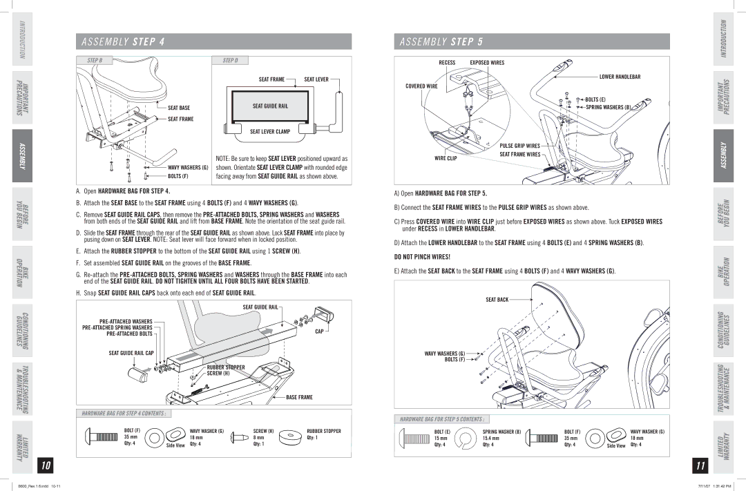
A S S E M B LY STEP 5
INTRODUCTION
IMPORTANT PRECAUTIONS
ASSEMBLY
STEP B
![]() SEAT BASE
SEAT BASE
![]()
![]() SEAT FRAME
SEAT FRAME
![]()
![]() WAVY WASHERS (G)
WAVY WASHERS (G)
![]()
![]() BOLTS (F)
BOLTS (F)
STEP D
SEAT FRAMESEAT GUIDE RAILSEAT LEVER
SEAT LEVER CLAMP
SEAT GUIDE RAIL
SEAT LEVER CLAMP
NOTE: Be sure to keep SEAT LEVER positioned upward as shown. Orientate SEAT LEVER CLAMP with rounded edge facing away from SEAT GUIDE RAIL as shown above.
RECESS | EXPOSED WIRES |
| LOWER HANDLEBAR |
COVERED WIRE |
|
| BOLTS (E) |
| SPRING WASHERS (B) |
| PULSE GRIP WIRES |
WIRE CLIP | SEAT FRAME WIRES |
|
IMPORTANT PRECAUTIONS
ASSEMBLY
BEFORE
YOU BEGIN
BIKE
OPERATION
CONDITIONING TROUBLESHOOTING LIMITED
GUIDELINES & MAINTENANCE WARRANTY
10
A.Open HARDWARE BAG FOR STEP 4.
B.Attach the SEAT BASE to the SEAT FRAME using 4 BOLTS (F) and 4 WAVY WASHERS (G).
C.Remove SEAT GUIDE RAIL CAPS, then remove the
D.Slide the SEAT FRAME through the rear of the SEAT GUIDE RAIL as shown above. Lock SEAT FRAME into place by pusing down on SEAT LEVER. NOTE: Seat lever will face forward when in locked position.
E.Attach the RUBBER STOPPER to the bottom of the SEAT GUIDE RAIL using 1 SCREW (H).
F.Set assembled SEAT GUIDE RAIL on the grooves of the BASE FRAME.
G.
H.Snap SEAT GUIDE RAIL CAPS back onto each end of SEAT GUIDE RAIL.
| SEAT GUIDE RAIL | |
| ||
CAP | ||
|
SEAT GUIDE RAIL CAP
RUBBER STOPPER
SCREW (H)
![]()
![]() BASE FRAME
BASE FRAME
HARDWARE BAG FOR STEP 4 CONTENTS :
BOLT (F) | WAVY WASHER (G) | SCREW (H) | RUBBER STOPPER |
35 mm | 18 mm | 8 mm | Qty: 1 |
Qty: 4 | Side View Qty: 4 | Qty: 1 |
|
A) Open HARDWARE BAG FOR STEP 5.![]() B) Connect the SEAT FRAME WIRES to the PULSE GRIP WIRES as shown above.
B) Connect the SEAT FRAME WIRES to the PULSE GRIP WIRES as shown above.
C) Press COVERED WIRE into WIRE CLIP just before EXPOSED WIRES as shown above. Tuck EXPOSED WIRES under RECESS in LOWER HANDLEBAR.
D) Attach the LOWER HANDLEBAR to the SEAT FRAME using 4 BOLTS (E) and 4 SPRING WASHERS (B).
DO NOT PINCH WIRES!
E)Attach the SEAT BACK to the SEAT FRAME using 4 BOLTS (F) and 4 WAVY WASHERS (G).
SEAT BACK |
WAVY WASHERS (G) |
BOLTS (F) |
HARDWARE BAG FOR STEP 5 CONTENTS :
BOLT (E) | SPRING WASHER (B) | BOLT (F) | WAVY WASHER (G) |
15 mm | 15.4 mm | 35 mm | 18 mm |
Qty: 4 | Qty: 4 | Qty: 4 | Side View Qty: 4 |
11
BEFORE YOU BEGIN
BIKE OPERATION
LIMITED TROUBLESHOOTING CONDITIONING WARRANTY & MAINTENANCE GUIDELINES
B600_Rev.1.6.indd | 7/11/07 1:31:42 PM |