HR24A specifications
The Hoshizaki HR24A is an advanced refrigeration unit designed to meet the cooling needs of commercial kitchens and food storage facilities. Known for its reliability and efficiency, this model showcases several innovative features that set it apart in the competitive market of commercial refrigeration.One of the standout characteristics of the Hoshizaki HR24A is its robust construction. Built with a durable stainless steel exterior, it not only adds aesthetic appeal but also ensures longevity and resistance to corrosion and wear. The interior is designed for easy cleaning, with rounded corners that minimize the buildup of grime and food particles.
The HR24A offers an impressive storage capacity, making it ideal for establishments with high-volume food storage requirements. With a temperature range typically between 33°F and 38°F, the unit maintains optimal conditions for preserving perishables such as meats, dairy, and vegetables. This precision in temperature control is essential for maintaining food safety and quality.
One of the key technologies integrated into the Hoshizaki HR24A is its advanced refrigeration system. Utilizing a highly efficient compressor and a fan-assisted cooling feature, the unit ensures rapid temperature recovery even in busy kitchen environments. This is crucial during peak hours when door openings are frequent, as it helps maintain consistent internal temperatures.
Energy efficiency is another hallmark of the HR24A. It is designed with environmentally friendly refrigerants and complies with Energy Star standards, which can lead to significant cost savings over time through reduced electricity consumption. This commitment to environmental responsibility makes it an attractive option for eco-conscious businesses.
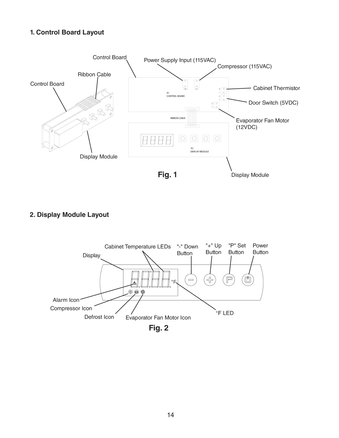
In terms of user-friendliness, the HR24A is equipped with digital controls and adjustable shelving, allowing for customized organization according to specific storage needs. The LED lighting inside the unit provides excellent visibility, making it easy to locate items quickly, which is particularly beneficial during busy service periods.
Overall, the Hoshizaki HR24A combines durability, efficiency, and functionality, making it an exceptional choice for anyone seeking a reliable refrigeration solution in a commercial kitchen setting. Whether used in restaurants, hotels, or catering businesses, its impressive features and state-of-the-art technology continue to meet the demanding requirements of the foodservice industry.

