E. Installation of the Condensing Unit
CAUTION
1.Failure to install the equipment within these guidelines may adversely affect performance, component life, and warranty coverage
2.Power supply and ground wire to the icemaker are supplied from the condensing unit. For details, see section "II.F. Electrical Connection."
1.Setup
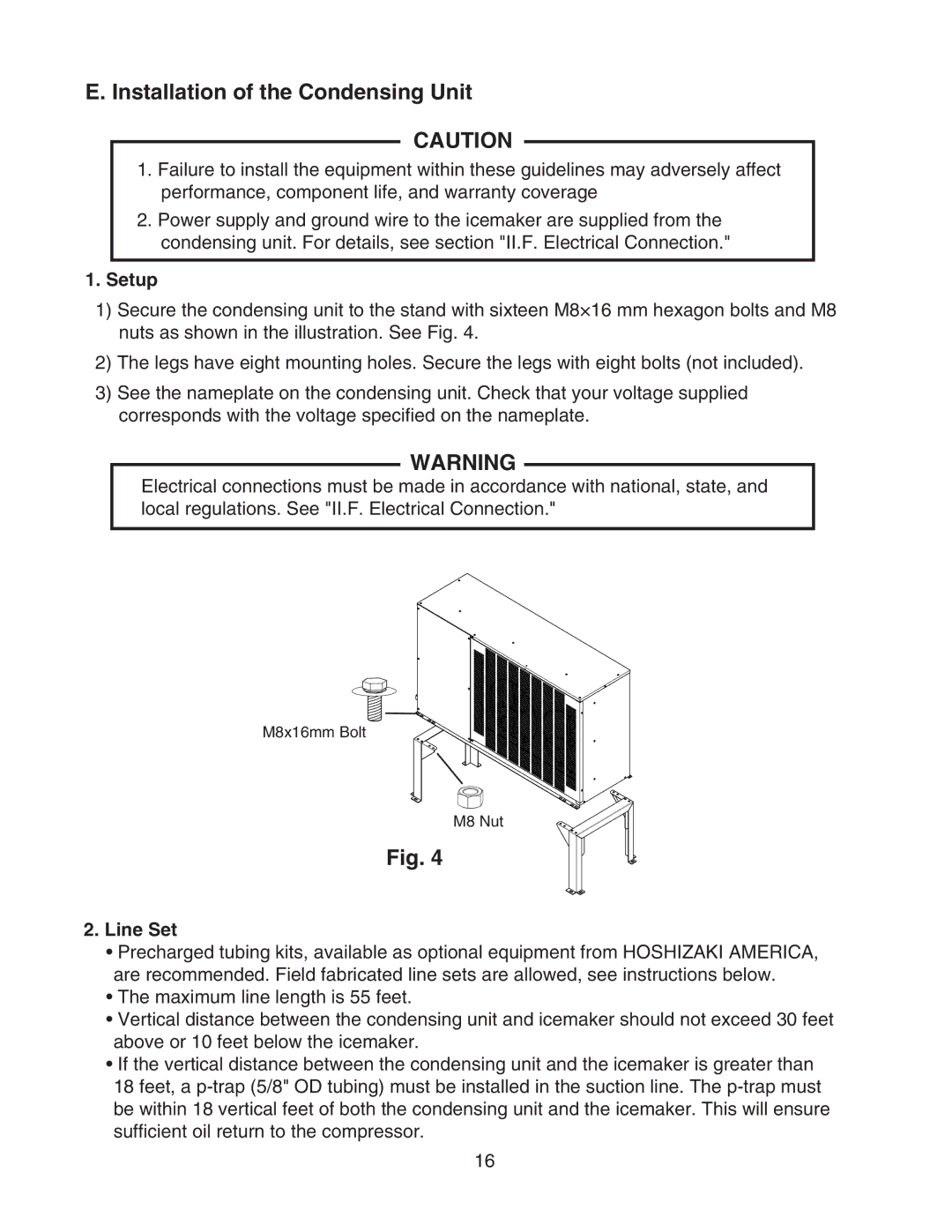
1)Secure the condensing unit to the stand with sixteen M8×16 mm hexagon bolts and M8 nuts as shown in the illustration. See Fig. 4.
2)The legs have eight mounting holes. Secure the legs with eight bolts (not included).
3)See the nameplate on the condensing unit. Check that your voltage supplied corresponds with the voltage specified on the nameplate.
WARNING
Electrical connections must be made in accordance with national, state, and local regulations. See "II.F. Electrical Connection."
M8x16mm Bolt
M8 Nut
Fig. 4
2.Line Set
•Precharged tubing kits, available as optional equipment from HOSHIZAKI AMERICA, are recommended. Field fabricated line sets are allowed, see instructions below.
•The maximum line length is 55 feet.
•Vertical distance between the condensing unit and icemaker should not exceed 30 feet above or 10 feet below the icemaker.
•If the vertical distance between the condensing unit and the icemaker is greater than 18 feet, a
16