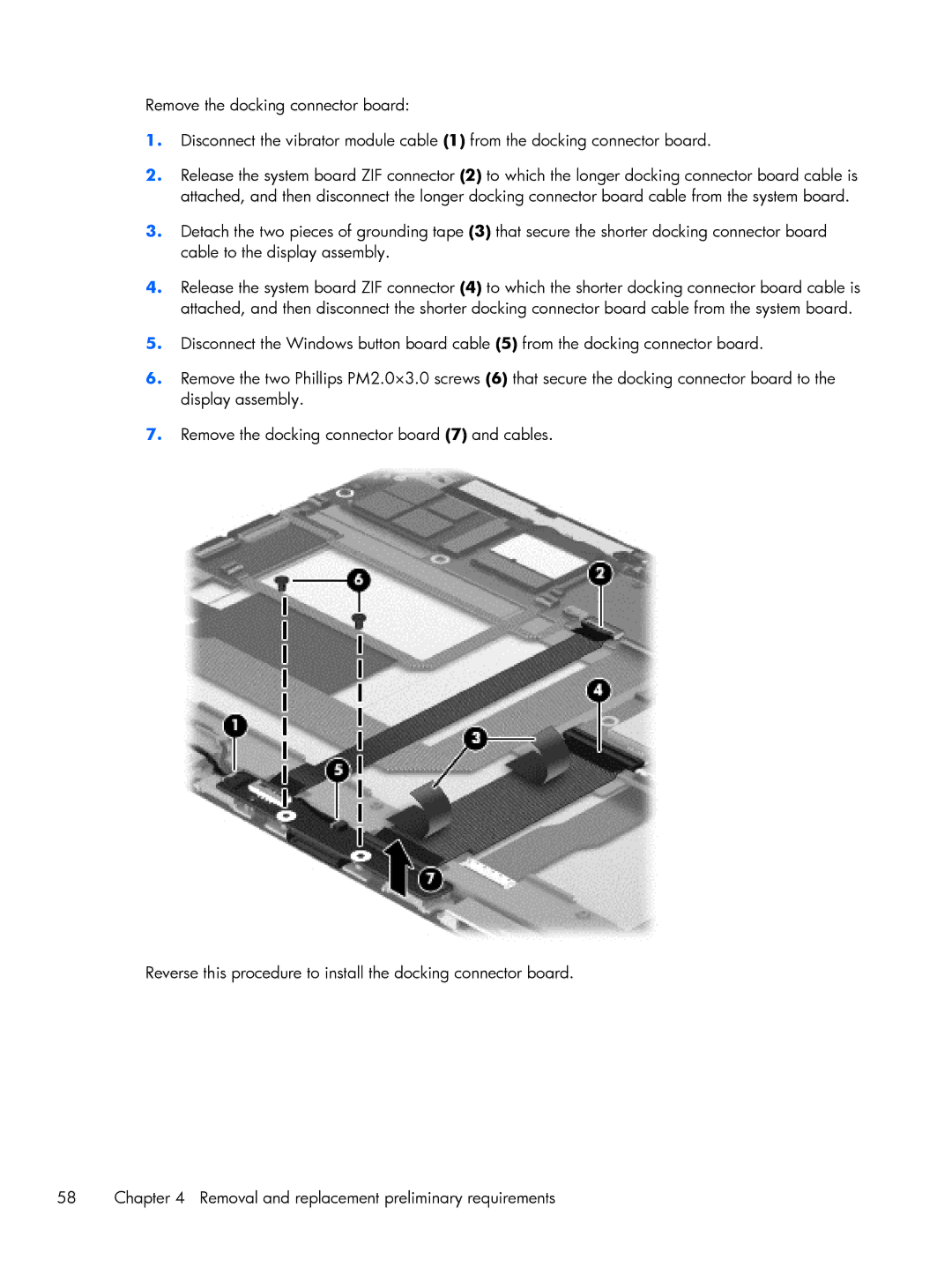
Remove the docking connector board:
1.Disconnect the vibrator module cable (1) from the docking connector board.
2.Release the system board ZIF connector (2) to which the longer docking connector board cable is attached, and then disconnect the longer docking connector board cable from the system board.
3.Detach the two pieces of grounding tape (3) that secure the shorter docking connector board cable to the display assembly.
4.Release the system board ZIF connector (4) to which the shorter docking connector board cable is attached, and then disconnect the shorter docking connector board cable from the system board.
5.Disconnect the Windows button board cable (5) from the docking connector board.
6.Remove the two Phillips PM2.0×3.0 screws (6) that secure the docking connector board to the display assembly.
7.Remove the docking connector board (7) and cables.
Reverse this procedure to install the docking connector board.
58 | Chapter 4 Removal and replacement preliminary requirements |