TB
(12)Adjust A9R7 Fine Adj. (fig. 3) and A9 Coarse Adj. (fig. 3) for a minimum indication on frequency difference meter.
(13)Disconnect TI from frequency difference meter.
(14)Reconnect TI rear panel 10 MHz OVEN OUTPUT to EXT REF IN.
13.Phase Increment
a.Performance Check
(1) Press keys and enter values using DATA keys as listed in (a) through (f) below:
(a)SIGNAL off (option 002 not lit).
(b)FUNCTION sine wave.
(c)ENTRY FREQ.
(d)100 kHz.
(e)ENTRY AMPTD.
(f)13 dBm.
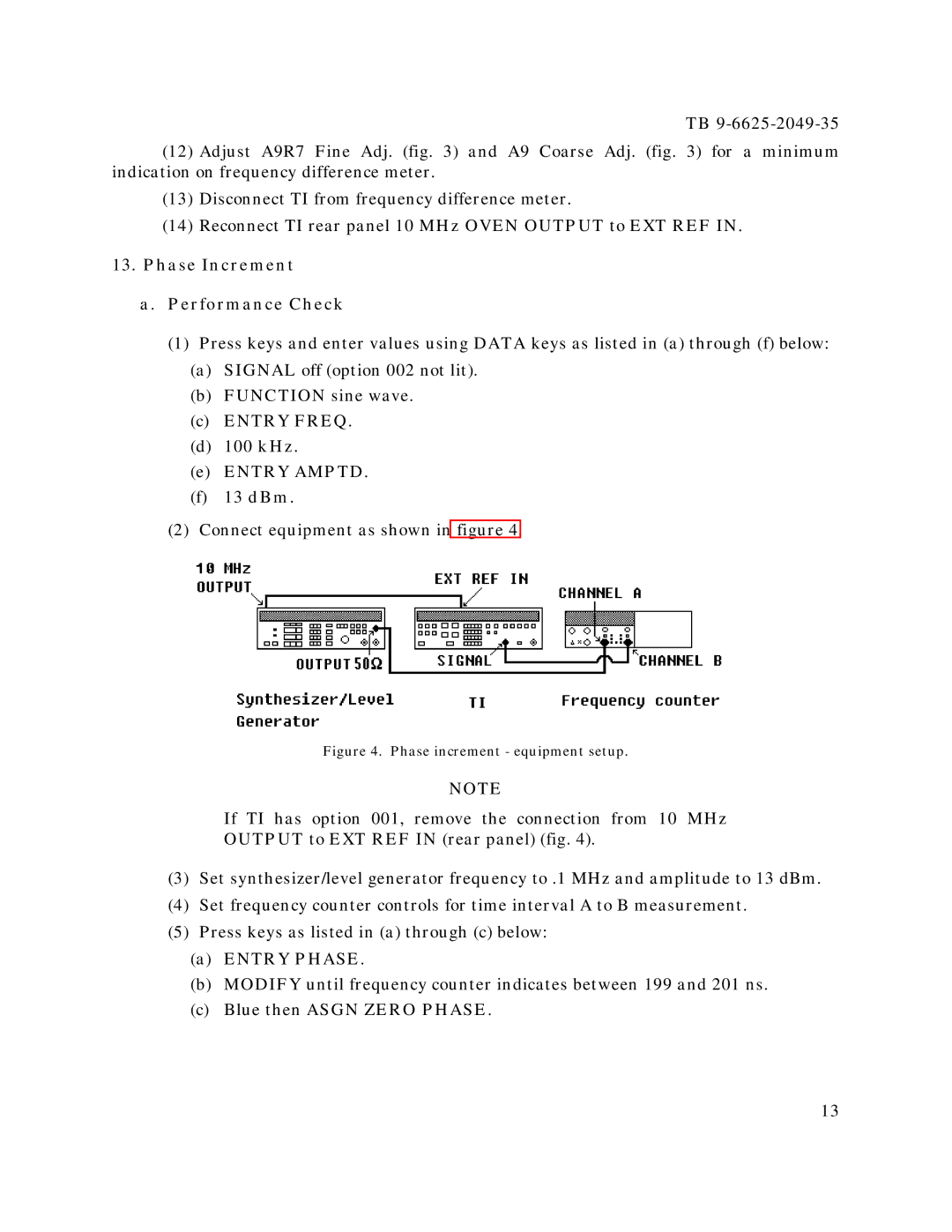
(2) Connect equipment as shown in figure 4.
Figure 4. Phase increment - equipment setup.
NOTE
If TI has option 001, remove the connection from 10 MHz
OUTPUT to EXT REF IN (rear panel) (fig. 4).
(3)Set synthesizer/level generator frequency to .1 MHz and amplitude to 13 dBm.
(4)Set frequency counter controls for time interval A to B measurement.
(5)Press keys as listed in (a) through (c) below:
(a)ENTRY PHASE.
(b)MODIFY until frequency counter indicates between 199 and 201 ns.
(c)Blue then ASGN ZERO PHASE.
13
