TB
9.Amplitude Modulation Distortion a. Performance Check
(1)Press keys and enter values using DATA keys as listed in (a) through (i) below:
(a)SIGNAL off (option 002 not lit).
(b)FUNCTION sine wave.
(c)ENTRY FREQ.
(d)1 MHz.
(e)ENTRY AMPTD.
(f)3 VOLT.
(g)ENTRY DC OFFSET.
(h)0 VOLT.
(i)Blue then AM ON.
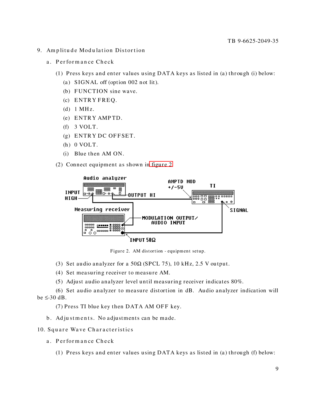
(2)Connect equipment as shown in figure 2.
Figure 2. AM distortion - equipment setup.
(3)Set audio analyzer for a 50Ω (SPCL 75), 10 kHz, 2.5 V output.
(4)Set measuring receiver to measure AM.
(5)Adjust audio analyzer level until measuring receiver indicates 80%.
(6)Set audio analyzer to measure distortion in dB. Audio analyzer indication will be
(7)Press TI blue key then DATA AM OFF key.
b.Adjustments. No adjustments can be made.
10.Square Wave Characteristics
a.Performance Check
(1)Press keys and enter values using DATA keys as listed in (a) through (f) below:
9
