TB
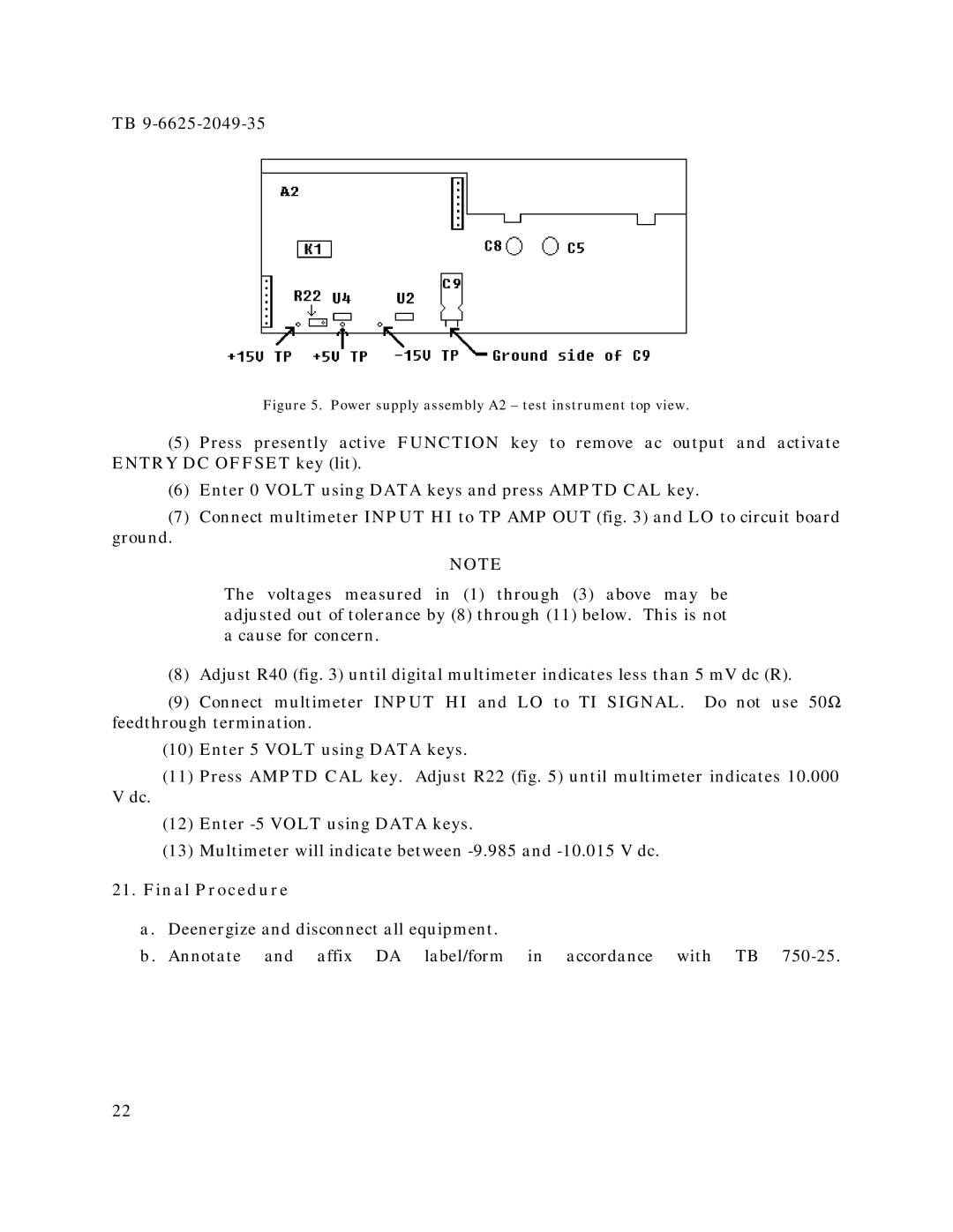
Figure 5. Power supply assembly A2 – test instrument top view.
(5)Press presently active FUNCTION key to remove ac output and activate ENTRY DC OFFSET key (lit).
(6)Enter 0 VOLT using DATA keys and press AMPTD CAL key.
(7)Connect multimeter INPUT HI to TP AMP OUT (fig. 3) and LO to circuit board
ground.
NOTE
The voltages measured in (1) through (3) above may be adjusted out of tolerance by (8) through (11) below. This is not a cause for concern.
(8)Adjust R40 (fig. 3) until digital multimeter indicates less than 5 mV dc (R).
(9)Connect multimeter INPUT HI and LO to TI SIGNAL. Do not use 50Ω feedthrough termination.
(10)Enter 5 VOLT using DATA keys.
(11)Press AMPTD CAL key. Adjust R22 (fig. 5) until multimeter indicates 10.000
V dc.
(12)Enter
(13)Multimeter will indicate between
21.Final Procedure
a. Deenergize and disconnect all equipment.
b. Annotate and affix DA label/form in accordance with TB
22