7.Insert drive blank into any slots without a disk drive. Push the drive blank until you detect a click. Figure 11 Inserting a drive blank
Cabling the enclosure
Two methods are described for cabling a new drive enclosure. The online method allows a drive enclosure to be added to a powered operational array. The offline method describes cabling an array that has been powered down. The offline method is preferred if downtime is available.
NOTE: One controller enclosure (with two controllers) can support up to eight drive enclosures.
The power cords are supplied in two different colors should you decide to use the colors to denote sides of the cabinet. For example, you can locate all gray power cords on the left side of the cabinet, and all black power cords on the right side.
Cabling the enclosure while offline
1.Power down the array.
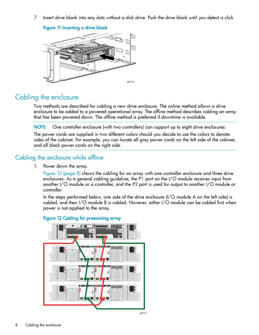
Figure 12 (page 8) shows the cabling for an array with one controller enclosure and three drive enclosures. As a general cabling guideline, the P1 port on the I/O module receives input from another I/O module or a controller, and the P2 port is used for output to another I/O module or controller.
In the steps performed below, one side of the drive enclosure (I/O module A on the left side) is cabled, and then I/O module B is cabled. However, either I/O module can be cabled first when power is not applied to the array.
Figure 12 Cabling for preexisting array
8Cabling the enclosure