Power and Signal Distribution
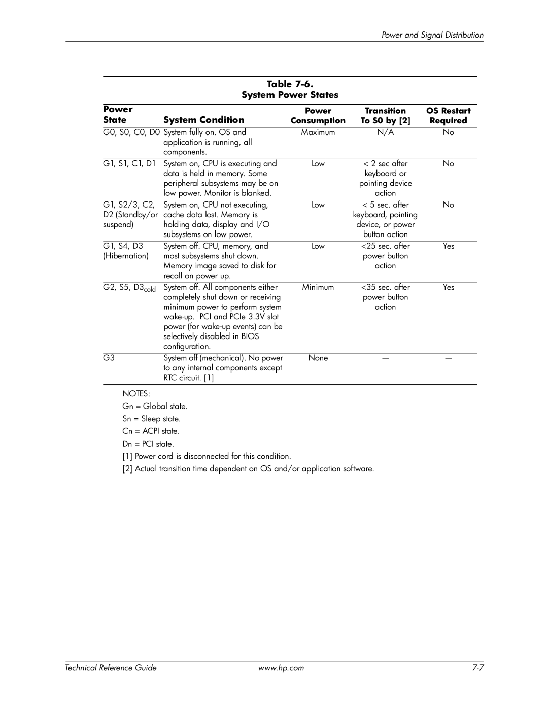
Table
System Power States
|
|
|
|
|
Power |
| Power | Transition | OS Restart |
State | System Condition | Consumption | To S0 by [2] | Required |
|
|
|
| |
G0, S0, C0, D0 System fully on. OS and | Maximum | N/A | No | |
| application is running, all |
|
|
|
| components. |
|
|
|
|
|
|
|
|
G1, S1, C1, D1 | System on, CPU is executing and | Low | < 2 sec after | No |
| data is held in memory. Some |
| keyboard or |
|
| peripheral subsystems may be on |
| pointing device |
|
| low power. Monitor is blanked. |
| action |
|
|
|
|
|
|
G1, S2/3, C2, | System on, CPU not executing, | Low | < 5 sec. after | No |
D2 (Standby/or | cache data lost. Memory is |
| keyboard, pointing |
|
suspend) | holding data, display and I/O |
| device, or power |
|
| subsystems on low power. |
| button action |
|
|
|
|
|
|
G1, S4, D3 | System off. CPU, memory, and | Low | <25 sec. after | Yes |
(Hibernation) | most subsystems shut down. |
| power button |
|
| Memory image saved to disk for |
| action |
|
| recall on power up. |
|
|
|
|
|
|
|
|
G2, S5, D3cold | System off. All components either | Minimum | <35 sec. after | Yes |
| completely shut down or receiving |
| power button |
|
| minimum power to perform system |
| action |
|
|
|
|
| |
| power (for |
|
|
|
| selectively disabled in BIOS |
|
|
|
| configuration. |
|
|
|
|
|
|
|
|
G3 | System off (mechanical). No power | None | — | — |
| to any internal components except |
|
|
|
| RTC circuit. [1] |
|
|
|
NOTES:
Gn = Global state.
Sn = Sleep state.
Cn = ACPI state.
Dn = PCI state.
[1]Power cord is disconnected for this condition.
[2]Actual transition time dependent on OS and/or application software.
| Technical Reference Guide | www.hp.com |
