Removal and Replacement Procedures
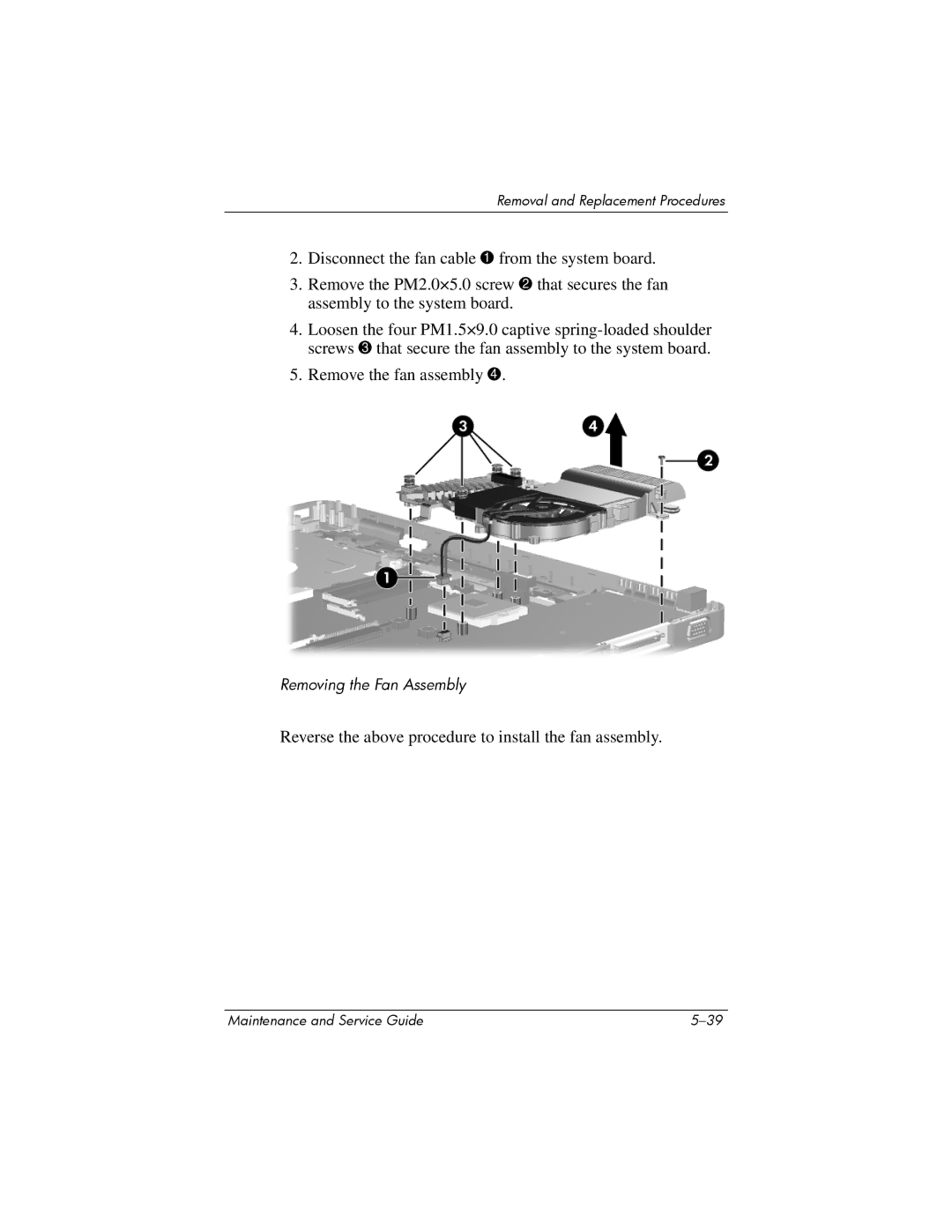
2.Disconnect the fan cable 1 from the system board.
3.Remove the PM2.0×5.0 screw 2 that secures the fan assembly to the system board.
4.Loosen the four PM1.5×9.0 captive
5.Remove the fan assembly 4.
Removing the Fan Assembly
Reverse the above procedure to install the fan assembly.
Maintenance and Service Guide |