5Removal and replacement procedures
![]()
![]() NOTE: This chapter provides removal and replacement procedures for Authorized Service Provider only components. Components described in this chapter should only be accessed by an authorized service provider. Accessing these components can damage the computer or void the warranty.
NOTE: This chapter provides removal and replacement procedures for Authorized Service Provider only components. Components described in this chapter should only be accessed by an authorized service provider. Accessing these components can damage the computer or void the warranty.
There are as many as 52 screws that must be removed, replaced, and/or loosened when servicing the computer. Make special note of each screw size and location during removal and replacement.
![]()
![]() NOTE: HP continually improves and changes product parts. For complete and current information on supported parts for your computer, go to http://partsurfer.hp.com, select your country or region, and then follow the
NOTE: HP continually improves and changes product parts. For complete and current information on supported parts for your computer, go to http://partsurfer.hp.com, select your country or region, and then follow the
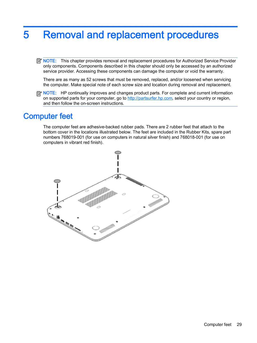
Computer feet
The computer feet are
Computer feet 29