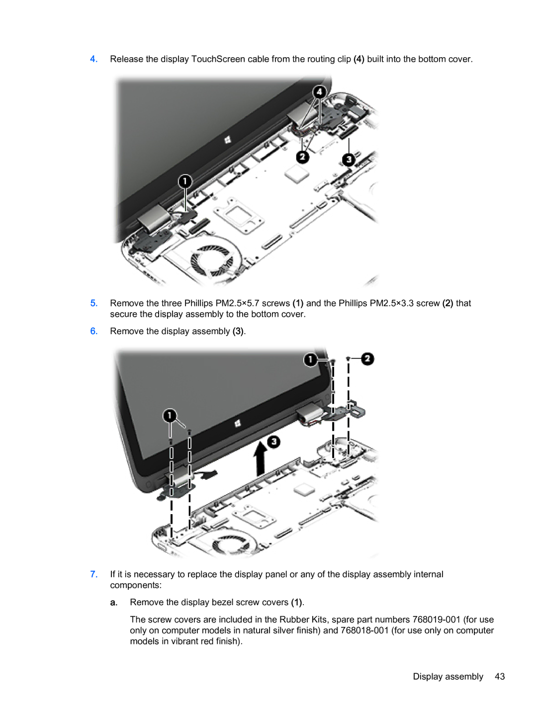
4.Release the display TouchScreen cable from the routing clip (4) built into the bottom cover.
5.Remove the three Phillips PM2.5×5.7 screws (1) and the Phillips PM2.5×3.3 screw (2) that secure the display assembly to the bottom cover.
6.Remove the display assembly (3).
7.If it is necessary to replace the display panel or any of the display assembly internal components:
a.Remove the display bezel screw covers (1).
The screw covers are included in the Rubber Kits, spare part numbers
Display assembly 43