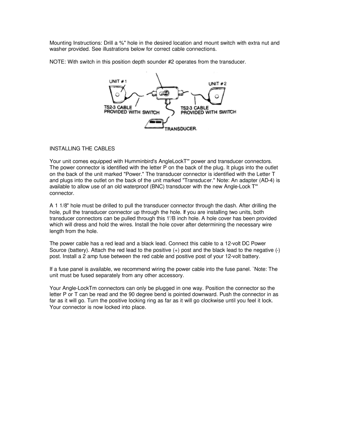
Mounting Instructions: Drill a %" hole in the desired location and mount switch with extra nut and washer provided. See illustrations below for correct cable connections.
NOTE: With switch in this position depth sounder #2 operates from the transducer.
INSTALLING THE CABLES
Your unit comes equipped with Humminbird's AngleLockT'" power and transducer connectors. The power connector is identified with the letter P on the back of the plug. It plugs into the outlet on the back of the unit marked "Power." The transducer connector is identified with the Letter T and plugs into the outlet on the back of the unit marked "Transducer." Note: An adapter
A 1 1/8" hole must be drilled to pull the transducer connector through the dash. After drilling the hole, pull the transducer connector up through the hole. If you are installing two units, both transducer connectors can be pulled through this 1'/B inch hole. A hole cover has been provided which will dress and hold the wires. Install the hole cover after determining the necessary wire length from the hole.
The power cable has a red lead and a black lead. Connect this cable to a
If a fuse panel is available, we recommend wiring the power cable into the fuse panel. `Note: The unit must be fused separately from any other accessory.
Your