Quick Installation Guide
Rosemount 3095 MultiVariable
STEP 2: TRANSMITTER INSTALLATION
Consider Housing Rotation
To improve field access or to better view the optional LCD display:
1.Loosen the housing rotation set screw.
2.Rotate the housing clockwise to the desired position – up to 180° from its original position. Over rotating will damage the transmitter.
3.If the desired position is attained, tighten the housing rotation set screw.
4.If the desired position cannot be reached because the housing will not rotate further, rotate the housing counterclockwise until in the desired position is attained (up to 180° from its original position).
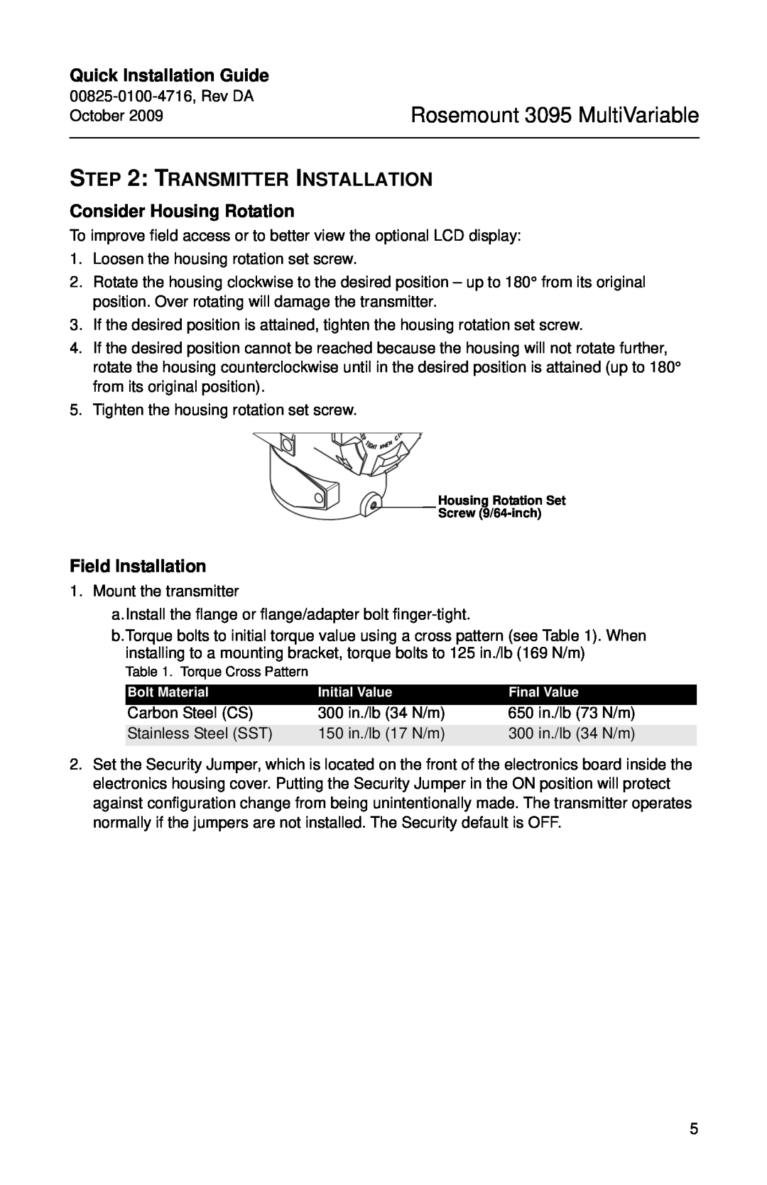
5.Tighten the housing rotation set screw.
Housing Rotation Set
![]()
![]()
![]() Screw
Screw
Field Installation
1. Mount the transmitter
a.Install the flange or flange/adapter bolt
b.Torque bolts to initial torque value using a cross pattern (see Table 1). When installing to a mounting bracket, torque bolts to 125 in./lb (169 N/m)
Table 1. Torque Cross Pattern
Bolt Material | Initial Value | Final Value |
Carbon Steel (CS) | 300 in./lb (34 N/m) | 650 in./lb (73 N/m) |
Stainless Steel (SST) | 150 in./lb (17 N/m) | 300 in./lb (34 N/m) |
2.Set the Security Jumper, which is located on the front of the electronics board inside the electronics housing cover. Putting the Security Jumper in the ON position will protect against configuration change from being unintentionally made. The transmitter operates normally if the jumpers are not installed. The Security default is OFF.
5