Manuals
/
Emerson
/
Marine Equipment
/
Marine Instruments
Emerson
00825-0100-4716
manual
Rosemount 3095 MultiVariable, Quick Installation Guide
Models:
00825-0100-4716
3095
1
32
32
Download
32 pages
51.72 Kb
25
26
27
28
29
30
31
32
Install
Signal Termination
Basic Configuration Parameters
RTD Connector
Consider Housing Rotation
Page 32
Image 32
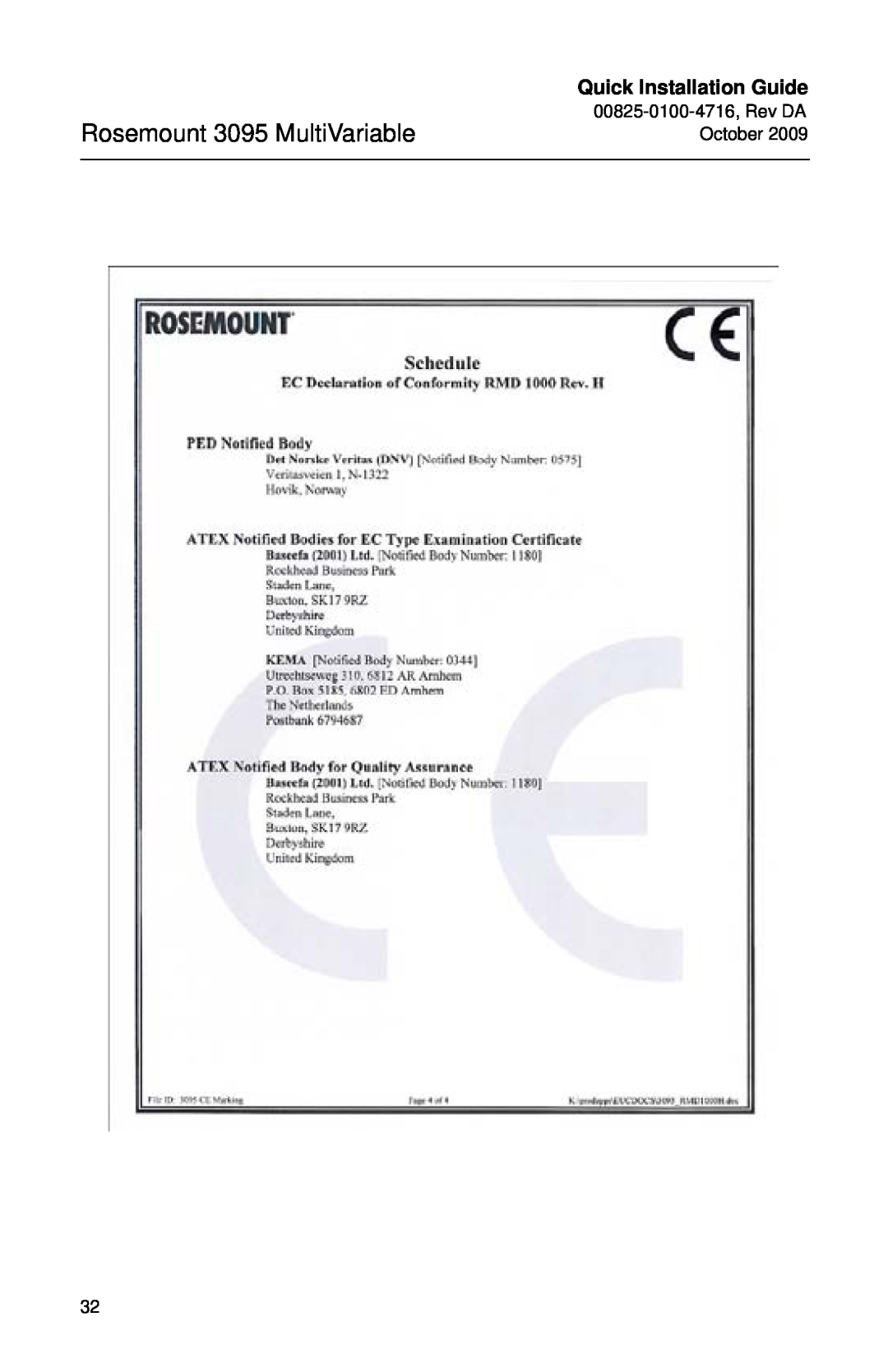
Quick Installation Guide
Rosemount 3095 MultiVariable
00825-0100-4716,
Rev DA October 2009
32
Page 31
Page 32
Page 32
Image 32
Page 31
Page 32
Contents
Quick Installation Guide
Rosemount 3095 MultiVariable
Fieldbus Protocol Rosemount 3095MF Series Flowmeter Transmitter
¢00825-0100-4716/¤
Explosions could result in death or serious injury
Process leaks may cause harm or result in death
Electrical shock can result in death or serious injury
IMPORTANT NOTICE
TRANSMITTER EXPLODED VIEW
RTD Connector
Terminal Block HART O-ring Cover
Certification Label Electronics Board Nameplate Module O-ring
STEP 1 MOUNT THE TRANSMITTER
Liquid Flow Applications
Gas Flow Applications
Steam Flow Applications
Field Installation
STEP 2 TRANSMITTER INSTALLATION
Consider Housing Rotation
Figure 3. Armored Shielded RTD Cable
STEP 2 CONTINUED
Figure 2. Alarm Jumper Location
Cable Adapter 1/2-14 NPT Black Cable Connector
Cable Gland Black Cable Connector/ RTD Connector
Figure 4. Shielded RTD Cable
Figure 5. ATEX/IECEx Flameproof RTD Cable
Bolting Considerations
Figure 6. Common Transmitter Assemblies
O-rings with Flange Adapters
Flange Adapter
O-ring
PTFE Based
STEP 3 SOFTWARE INSTALLATION
3095 Engineering Assistant EA for HART Software Installation
Installing the HART Modem
3095 Engineering Assistant EA for FOUNDATION Fieldbus
STEP 3 CONTINUED
3. Select Hart Modem
STEP 4 CONNECT WIRING AND POWER UP HART
24 Vdc Supply Current RL≥ 250Ω Meter
STEP 4 CONNECT WIRING AND POWER UP FIELDBUS
Power Supply
Power Conditioner
Shield Wire Ground
STEP 5 CONFIGURE THE TRANSMITTER HART
Setting the Loop to Manual
Send the Configuration to the Transmitter
Basic Configuration Parameters
Quick Installation Guide
AI Block configuration parameters
STEP 5 CONFIGURE THE TRANSMITTER FIELDBUS
To configure the AI Block
Using the Field Communicator
Using the Foundation Fieldbus AI Block
Using the Foundation Fieldbus Host System
STEP 6 TRIM THE TRANSMITTER
PRODUCT CERTIFICATIONS Rosemount 3095 with HART
Approved Manufacturing Locations
European Directive Information
Rosemount 3095 HART Hazardous Locations Certifications
Special Conditions for Safe Use
Canadian Standards Association CSA
European Certifications
IECEx Certifications HART
Conditions of Certification
INMETRO Certifications
L i ≈
China NEPSI Certifications
Special conditions for safe use
Maximum Temperature of
Rosemount 3095 with Fieldbus
Combinations of Certifications
ATEX Directive 94/9/EC
European Pressure Equipment Directive PED 97/23/EC
Rosemount 3095 Fieldbus Hazardous Locations Certifications
North American Certifications
FM Approvals
Canadian Standards Association CSA
Quick Installation Guide
IECEx Certifications Fieldbus
Combinations of Certifications
Quick Installation Guide
Rosemount 3095 MultiVariable
Quick Installation Guide
Rosemount 3095 MultiVariable
Quick Installation Guide
Rosemount 3095 MultiVariable
Quick Installation Guide
Rosemount 3095 MultiVariable
Quick Installation Guide
Rosemount 3095 MultiVariable
Top
Page
Image
Contents