18 ProFlex, 20 ProFlex specifications
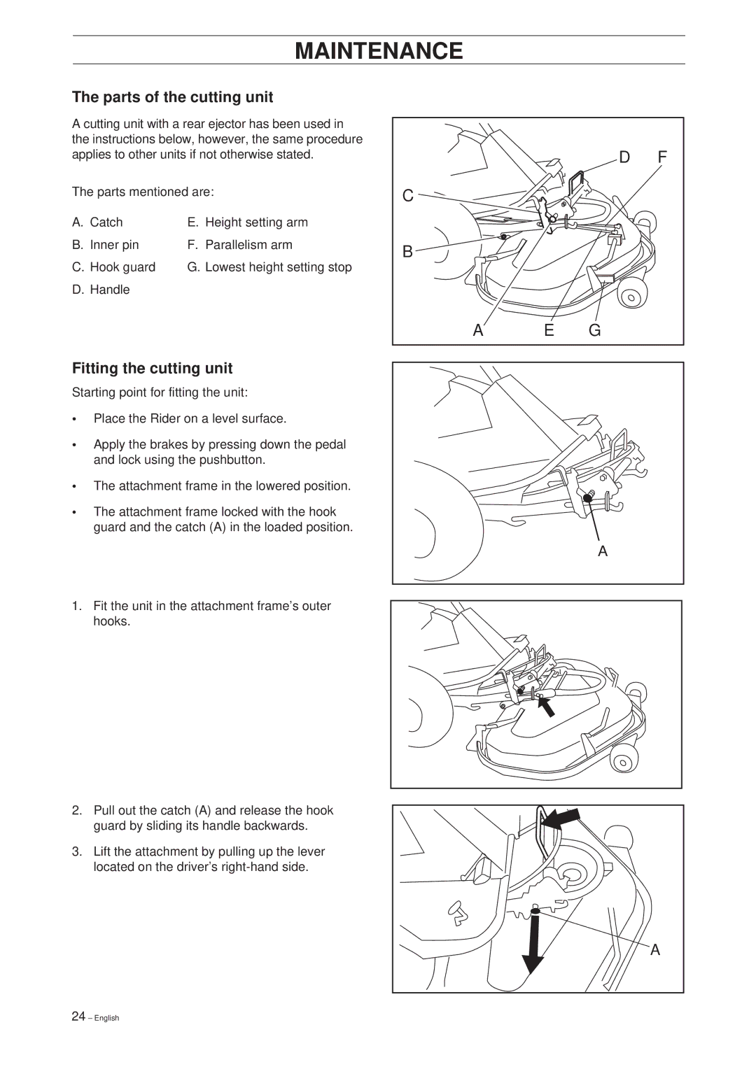
Husqvarna, a trusted name in outdoor power equipment, has unveiled its latest offerings in the ride-on mower segment with the Husqvarna 18 ProFlex and 20 ProFlex models. These machines are designed to provide superior performance for both professional landscapers and avid gardening enthusiasts. The ProFlex series is characterized by its advanced engineering, making it ideal for tackling varied terrains and challenging mowing tasks effectively.One of the standout features of both models is the innovative cutting system. Each mower is equipped with a high-performance cutting deck that utilizes a cutting width of 48 inches for the 18 ProFlex and 54 inches for the 20 ProFlex. This deck configuration allows for precise cutting, ensuring a clean and efficient mow, while also reducing the number of passes needed for larger areas. The adjustable cutting height further enhances flexibility, allowing users to choose the perfect setting for different grass types and conditions.
The Husqvarna ProFlex series also incorporates advanced technology that makes mowing easier and more efficient. The integrated intuitive control panel provides users with easy access to all essential functions, including mowing speed and blade engagement. The models feature a powerful engine, delivering robust performance and reliability even in challenging weather conditions. The 20 ProFlex is particularly noted for its impressive horsepower, enabling it to handle tougher terrains without compromising on efficiency.
Durability is another key characteristic of the ProFlex series. Both the 18 and 20 models are built with high-quality materials and boast a rugged chassis designed to withstand the rigors of regular use. This durability is complemented by superior ergonomics, ensuring that operators experience comfort during extended operation. The adjustable seat and steering wheel facilitate a customized fit for operators of all sizes.
In addition, Husqvarna has integrated advanced safety features into the ProFlex models. The automatic brake system enhances user safety by engaging whenever the operator leaves the seat, ensuring peace of mind during operation.
In conclusion, the Husqvarna 18 ProFlex and 20 ProFlex offer a blend of power, efficiency, and user-centric design. With their robust features, advanced technologies, and commitment to safety, these ride-on mowers are sure to meet the demands of both professional and residential users who seek to maintain pristine lawns and gardens. Whether tackling large properties or navigating tight spaces, the ProFlex series stands ready to deliver high-quality results.

