INSTALLATION
The Auto Mower can mow |
|
|
areas with an incline of up to |
|
|
around 15° (27 cm difference in |
|
|
height per metre). Steeper |
|
|
areas must be cordoned off | 15 |
|
with the boundary wire. If the |
| |
|
| |
optional weights are fitted |
|
|
(article number 535 09 | 45 | 15 |
the mower can tackle inclines slightly steeper than 15°. You should however avoid laying the boundary wire on a downslope. When the grass is wet the mower may slip if the slope is too steep, and it might have problems reversing when it reaches the wire.
Lay out the boundary wire and secure it to the ground using staples so that there is no risk of the blades cutting the cable. Allow the Auto Mower to work for a week and then decide whether any adjustments to the wire routing are necessary. After a few weeks the grass will have “weaved in” the cable so that it is not visible. The boundary cable can also be laid
Metallic objects can interfere with the boundary signal. The boundary wire should therefore not be routed too close to iron fences or metal manhole covers. In most cases it is sufficient to lay the boundary wire 30 cm from these types of object. How- ever, in some cases, such as electric fences, the distance may need to be greater. If the Auto Mower regularly stops at a certain point on the lawn and indicates that there is no signal from the wire (LED 6 is on), this is probably due to this kind of interference.
If the boundary wire needs to be joined this must be done so that the joint is waterproof. The best contact is obtained if the joint is made using Husqvarna’s
535 04
NOTE! Twisted cable ends or a single screw terminal block, insulated with insulation tape are not satisfactory joints. Ground moisture causes the conductors to oxidise and after a period of time this will result in a breakage in the circuit.
Outlining areas inside the working area
If you wish, you can keep the Auto Mower away from certain places within the working area, such as flowerbeds, fountains etc. Route the boundary wire out to the section, around the section and then back along the same route as the boundary wire was taken out. The same instructions also apply when the boundary wire is being taken out to an area that lies outside the first delimited working area. The cables should be laid close to each other. If the cables are stapled, they should be placed under the same staples.
NOTE! It is very important to route the boundary wire in the correct direction around the section, so that it does not crossover itself, see the illustration.
minimised
Trees, bushes and the like that can withstand the Auto Mower pushing against them do not need to be screened off by the boundary wire. The Auto Mower will reverse anyway when it hits an obstacle. However, these obstacles must be higher than the front edge of the chassis, which means about 10 cm or more. Similarly, obstacles with a gentle slope, for example stones or large trees with protruding roots, should be either screened off or removed. Otherwise the Auto Mower can climb up on such obstacles and probably damage its blades.
Installation of search loop
When it’s time to charge the battery, the Auto Mower begins to look for the search wire. Once the Auto Mower has detected that it has crossed the search wire, it follows the wire in a clockwise direction until it reaches the docking side of the charging station. Searching for the search wire begins when there is enough charge left in the battery for another hour or two of running time. At some time during this period the Auto Mower must therefore find the search wire. If the Auto Mower has plenty of charge left in its battery, it will ignore the search wire.
The search wire must be laid from the charging station clockwise around but inside the working area and then back to the charging station. If the working area consists of several sections that are joined to each other by passages, the search wire must be laid so that it goes into each area. See “Planning installation” for examples.
The search wire must never go outside the working area or crosso- ver itself.
Passages and wire separation distance
Lay the search wire as straight as possible. Make sharp corners wherever the wire needs to turn. Refer to “Installation of boundary wire” for advice on possible signal interference from the sur- roundings.
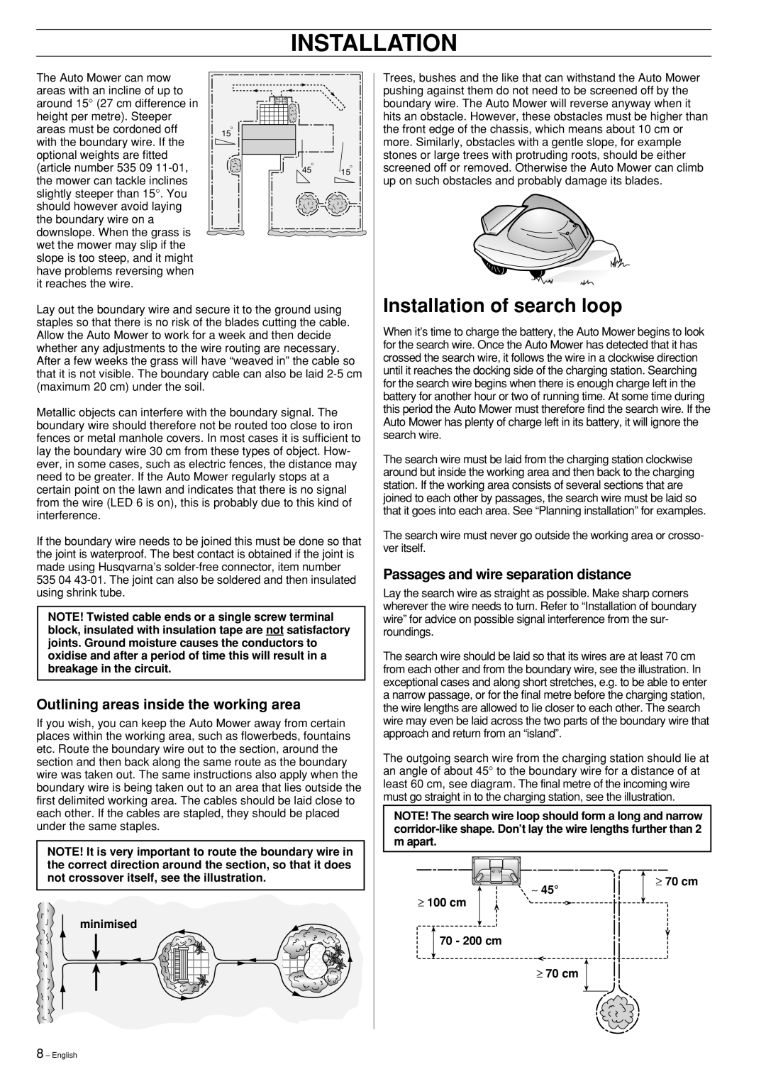
The search wire should be laid so that its wires are at least 70 cm from each other and from the boundary wire, see the illustration. In exceptional cases and along short stretches, e.g. to be able to enter a narrow passage, or for the final metre before the charging station, the wire lengths are allowed to lie closer to each other. The search wire may even be laid across the two parts of the boundary wire that approach and return from an “island”.
The outgoing search wire from the charging station should lie at an angle of about 45° to the boundary wire for a distance of at least 60 cm, see diagram. The final metre of the incoming wire must go straight in to the charging station, see the illustration.
NOTE! The search wire loop should form a long and narrow
≥ 70 cm
∼ 45°
≥ 100 cm
70 - 200 cm
≥70 cm
8 – English