| Run |
f | P |
f | r |
O | e |
| - |
| he |
| a |
| t |
| S |
| t |
| a |
| r |
| t |
A Ignition switch | |
| Figure 3-2 |
BHead light switch
Figure 3-3
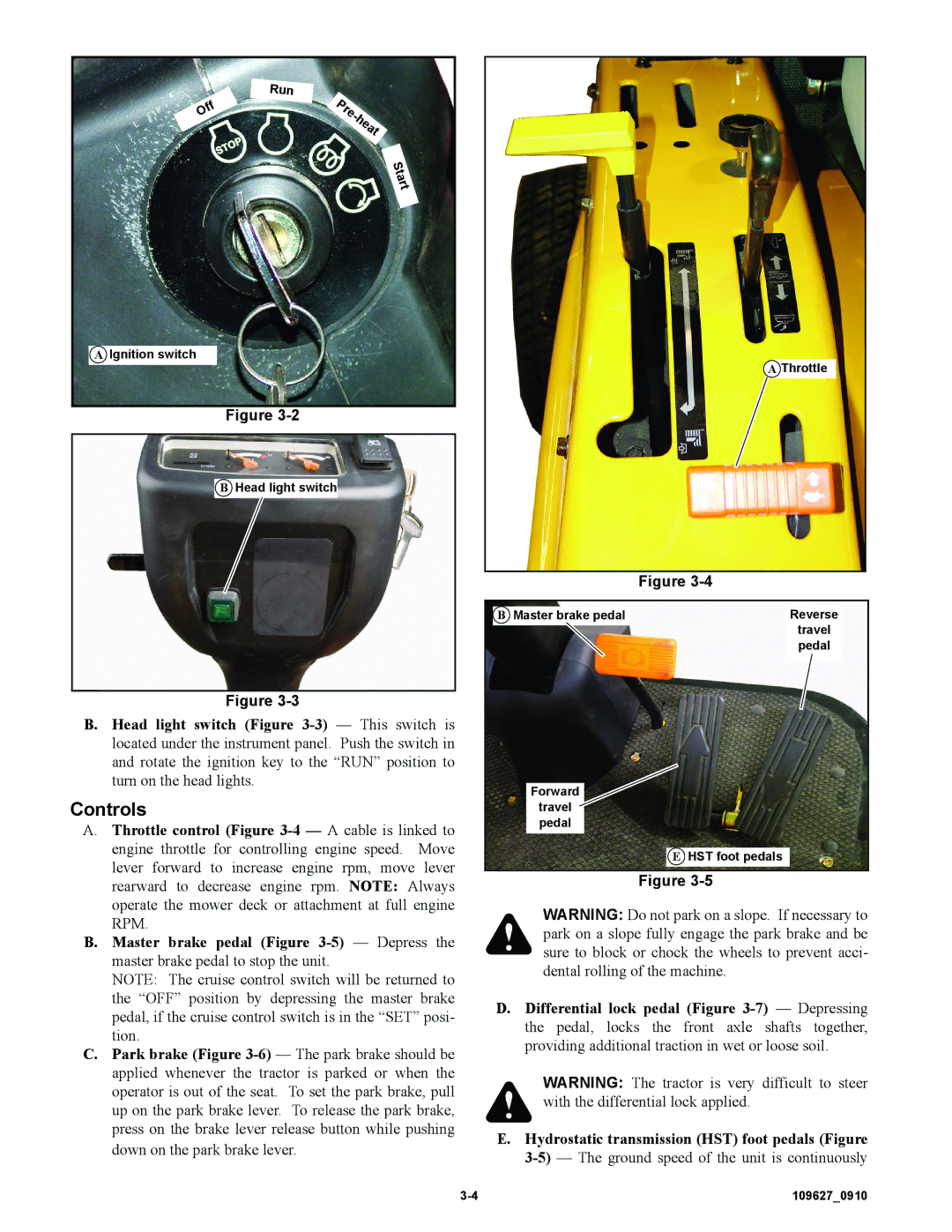
B.Head light switch (Figure 3-3) — This switch is located under the instrument panel. Push the switch in and rotate the ignition key to the “RUN” position to turn on the head lights.
Controls
A.Throttle control (Figure 3-4 — A cable is linked to engine throttle for controlling engine speed. Move lever forward to increase engine rpm, move lever rearward to decrease engine rpm. NOTE: Always operate the mower deck or attachment at full engine RPM.
B.Master brake pedal (Figure 3-5) — Depress the master brake pedal to stop the unit.
NOTE: The cruise control switch will be returned to the “OFF” position by depressing the master brake pedal, if the cruise control switch is in the “SET” posi- tion.
C.Park brake (Figure 3-6)— The park brake should be applied whenever the tractor is parked or when the operator is out of the seat. To set the park brake, pull up on the park brake lever. To release the park brake, press on the brake lever release button while pushing down on the park brake lever.
A Throttle
| Figure 3-4 |
B Master brake pedal | Reverse |
| travel |
| pedal |
Forward | |
travel | |
pedal | |
| E HST foot pedals |
| Figure 3-5 |
WARNING: Do not park on a slope. If necessary to park on a slope fully engage the park brake and be sure to block or chock the wheels to prevent acci- dental rolling of the machine.
D.Differential lock pedal (Figure 3-7) — Depressing the pedal, locks the front axle shafts together, providing additional traction in wet or loose soil.
WARNING: The tractor is very difficult to steer with the differential lock applied.
E.Hydrostatic transmission (HST) foot pedals (Figure 3-5) — The ground speed of the unit is continuously

