Final reduction gear ![]() case fill plug
case fill plug
Figure
resistance (50% into the control lever stroke). A reading of
NOTE: The adjustment bolt on the PTO adjustment linkage uses
3.Loosen the locknuts on the PTO adjustment linkage. Figure
4.Turn the adjustment rod and recheck the resistance on the pull scale and the control lever stroke. Repeat this step until the control lever stroke and the pull resistance are correct.
5.Tighten the locknuts.
Locknuts
Linkage
Figure
General engine maintenance
Detailed instructions and recommendations for
Park brake adjustment
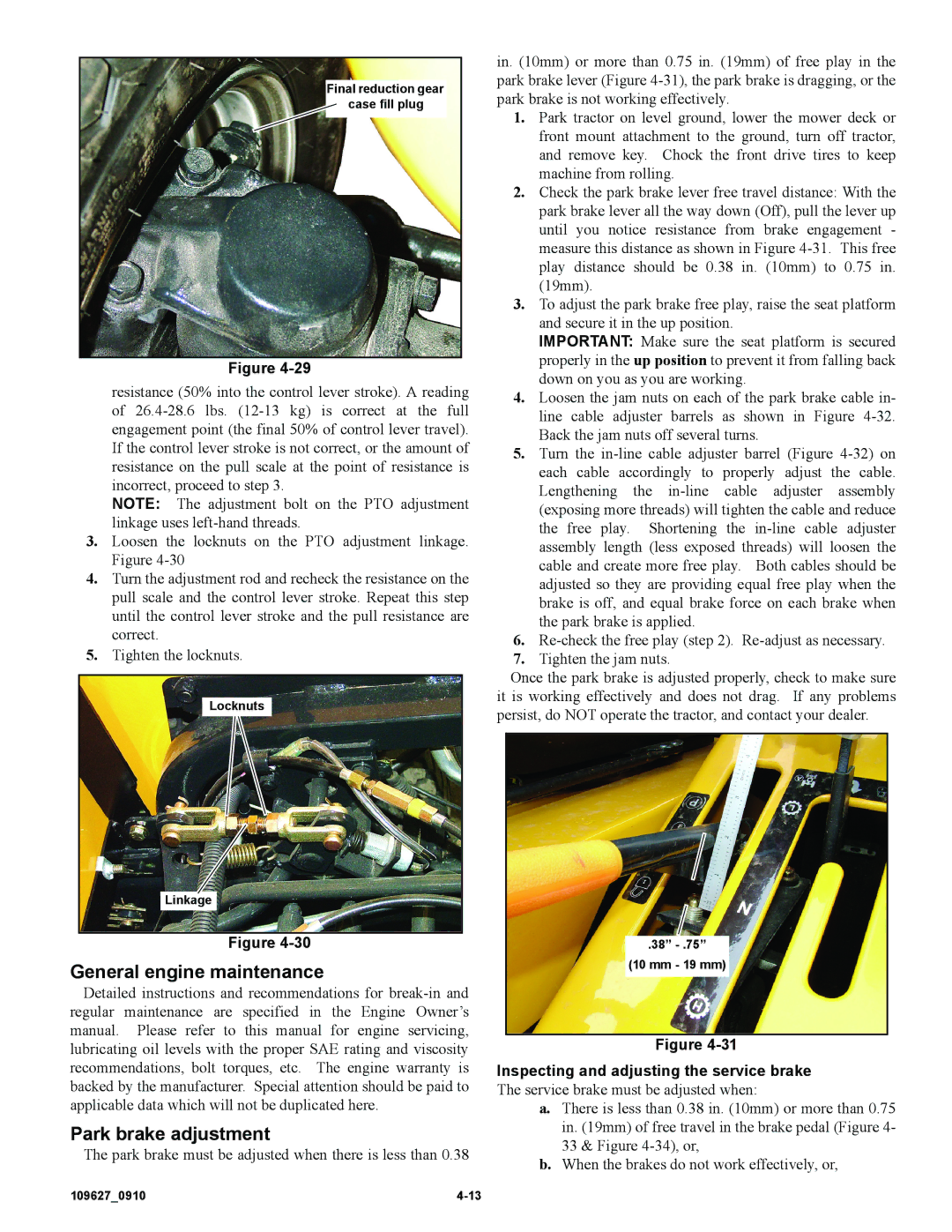
The park brake must be adjusted when there is less than 0.38
in. (10mm) or more than 0.75 in. (19mm) of free play in the park brake lever (Figure
1.Park tractor on level ground, lower the mower deck or front mount attachment to the ground, turn off tractor, and remove key. Chock the front drive tires to keep machine from rolling.
2.Check the park brake lever free travel distance: With the park brake lever all the way down (Off), pull the lever up until you notice resistance from brake engagement - measure this distance as shown in Figure
3.To adjust the park brake free play, raise the seat platform and secure it in the up position.
IMPORTANT: Make sure the seat platform is secured properly in the up position to prevent it from falling back down on you as you are working.
4.Loosen the jam nuts on each of the park brake cable in- line cable adjuster barrels as shown in Figure
5.Turn the
6.
7.Tighten the jam nuts.
Once the park brake is adjusted properly, check to make sure it is working effectively and does not drag. If any problems persist, do NOT operate the tractor, and contact your dealer.
.38”
(10 mm - 19 mm)
Figure
Inspecting and adjusting the service brake The service brake must be adjusted when:
a.There is less than 0.38 in. (10mm) or more than 0.75 in. (19mm) of free travel in the brake pedal (Figure 4- 33 & Figure
b.When the brakes do not work effectively, or,
109627_0910 |
