many other possibilities too numerous to mention. Just remember to always exercise extreme caution when operating on any slope.
The ROPS will minimize chance of injury or death from rollover. Seat belt must be fastened while oper- ating a machine equipped with ROPS in the raised and secured position. Both retaining pins and hair pins must be installed. Failure to use seat belt will result in serious injury in the event of a roll over.
Children
Tragic accidents can occur if the operator is not alert to the presence of children. Children are often attracted to the machine and the mowing activity. Never assume that children will remain where you last saw them.
Never leave machine unattended with ignition key in switch, especially with children present.
Children or bystanders may be injured if they move or attempt to operate the tractor while it is unattended. Always disengage PTO lever, engage park brake, stop tractor engine, and remove ignition key when leaving operator’s seat.
Keep children out of the mowing area and under the watchful care of a responsible adult other than the operator.
Be alert and turn the machine off if children enter the area.
Before and while backing, look behind and down for small children.
Never carry children, even with the blades off. They may fall off and be seriously injured or interfere with safe machine operation. Children who have been given rides in the past may suddenly appear in the mowing area for another ride and be run over or backed over by the machine.
Never allow children to operate the machine.
Use care when approaching blind corners, shrubs, trees, the end of a fence or other objects that may obscure vision.
Never allow children or others in or on towed equip- ment.
Instrument Panel
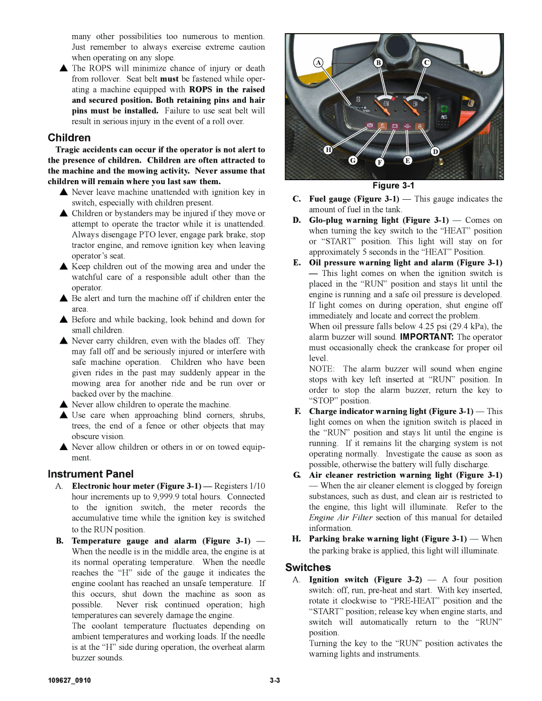
A.Electronic hour meter (Figure
B.Temperature gauge and alarm (Figure
The coolant temperature fluctuates depending on ambient temperatures and working loads. If the needle is at the “H” side during operation, the overheat alarm buzzer sounds.
ABC
HD
G F E
Figure
C.Fuel gauge (Figure
D.
E.Oil pressure warning light and alarm (Figure
—This light comes on when the ignition switch is placed in the “RUN” position and stays lit until the engine is running and a safe oil pressure is developed. If light comes on during operation, shut engine off immediately and locate and correct the problem.
When oil pressure falls below 4.25 psi (29.4 kPa), the alarm buzzer will sound. IMPORTANT: The operator must occasionally check the crankcase for proper oil level.
NOTE: The alarm buzzer will sound when engine stops with key left inserted at “RUN” position. In order to stop the alarm buzzer, return the key to “STOP” position.
F.Charge indicator warning light (Figure
G.Air cleaner restriction warning light (Figure
—When the air cleaner element is clogged by foreign substances, such as dust, and clean air is restricted to the engine, this light will illuminate. Refer to the Engine Air Filter section of this manual for detailed information.
H.Parking brake warning light (Figure
Switches
A.Ignition switch (Figure
Turning the key to the “RUN” position activates the warning lights and instruments.
109627_0910 |