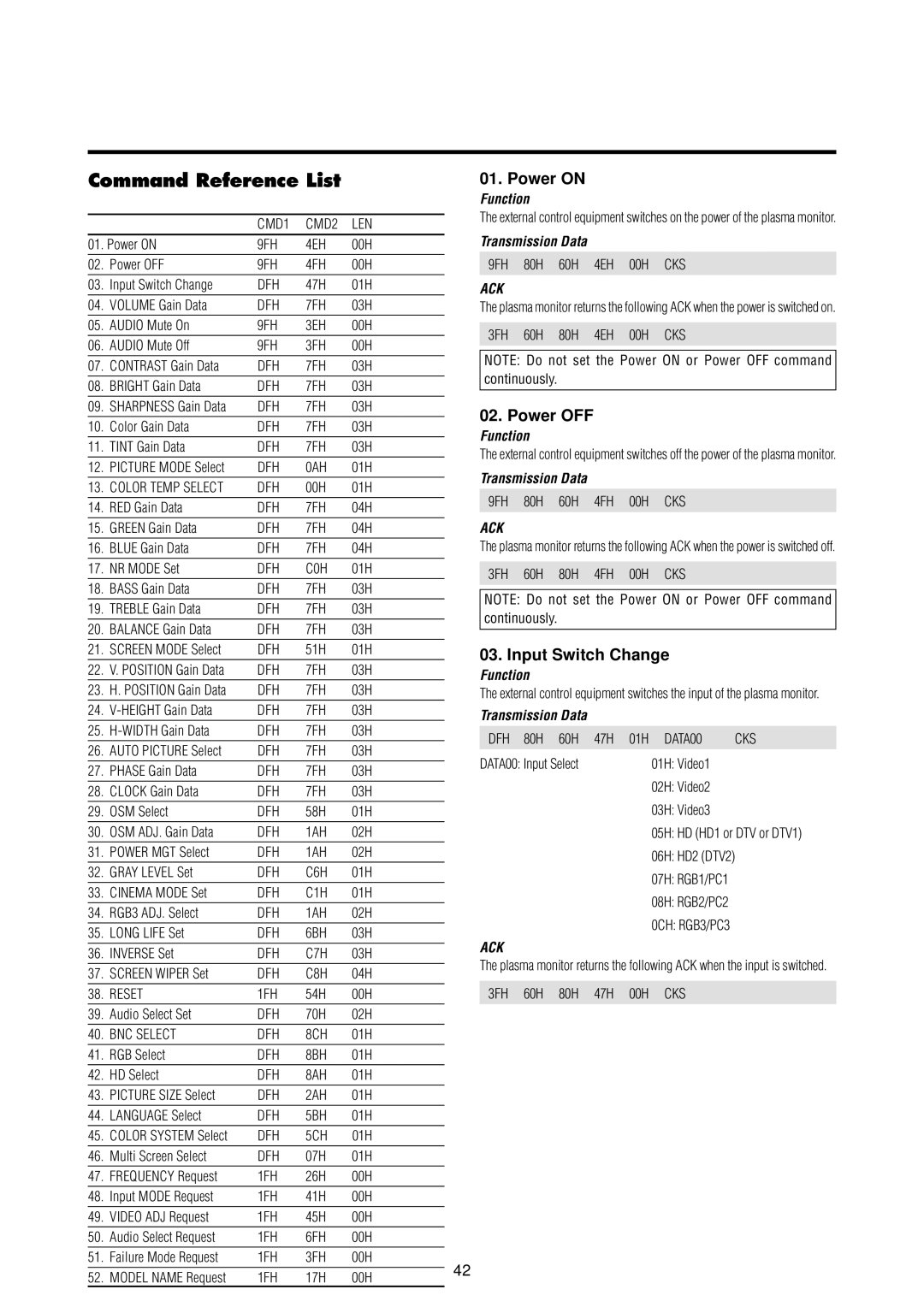
Command Reference List
|
| CMD1 | CMD2 | LEN |
| |
01. Power ON | 9FH | 4EH | 00H |
| ||
02. | Power OFF | 9FH | 4FH | 00H |
| |
03. | Input Switch Change | DFH | 47H | 01H |
| |
04. | VOLUME Gain Data | DFH | 7FH | 03H |
| |
05. | AUDIO Mute On | 9FH | 3EH | 00H |
| |
06. | AUDIO Mute Off | 9FH | 3FH | 00H |
| |
07. | CONTRAST Gain Data | DFH | 7FH | 03H |
| |
08. | BRIGHT Gain Data | DFH | 7FH | 03H |
| |
09. | SHARPNESS Gain Data | DFH | 7FH | 03H |
| |
10. | Color Gain Data | DFH | 7FH | 03H |
| |
11. | TINT Gain Data | DFH | 7FH | 03H |
| |
12. | PICTURE MODE Select | DFH | 0AH | 01H |
| |
13. | COLOR TEMP SELECT | DFH | 00H | 01H |
| |
14. | RED Gain Data | DFH | 7FH | 04H |
| |
15. | GREEN Gain Data | DFH | 7FH | 04H |
| |
16. | BLUE Gain Data | DFH | 7FH | 04H |
| |
17. | NR MODE Set | DFH | C0H | 01H |
| |
18. | BASS Gain Data | DFH | 7FH | 03H |
| |
19. | TREBLE Gain Data | DFH | 7FH | 03H |
| |
20. | BALANCE Gain Data | DFH | 7FH | 03H |
| |
21. | SCREEN MODE Select | DFH | 51H | 01H |
| |
22. | V. POSITION Gain Data | DFH | 7FH | 03H |
| |
23. | H. POSITION Gain Data | DFH | 7FH | 03H |
| |
24. | DFH | 7FH | 03H |
| ||
25. | DFH | 7FH | 03H |
| ||
26. | AUTO PICTURE Select | DFH | 7FH | 03H |
| |
27. | PHASE Gain Data | DFH | 7FH | 03H |
| |
28. | CLOCK Gain Data | DFH | 7FH | 03H |
| |
29. | OSM Select | DFH | 58H | 01H |
| |
30. | OSM ADJ. Gain Data | DFH | 1AH | 02H |
| |
31. | POWER MGT Select | DFH | 1AH | 02H |
| |
32. | GRAY LEVEL Set | DFH | C6H | 01H |
| |
33. | CINEMA MODE Set | DFH | C1H | 01H |
| |
34. | RGB3 ADJ. Select | DFH | 1AH | 02H |
| |
35. | LONG LIFE Set | DFH | 6BH | 03H |
| |
36. | INVERSE Set | DFH | C7H | 03H |
| |
37. | SCREEN WIPER Set | DFH | C8H | 04H |
| |
38. | RESET | 1FH | 54H | 00H |
| |
39. | Audio Select Set | DFH | 70H | 02H |
| |
40. | BNC SELECT | DFH | 8CH | 01H |
| |
41. | RGB Select | DFH | 8BH | 01H |
| |
42. | HD Select | DFH | 8AH | 01H |
| |
43. | PICTURE SIZE Select | DFH | 2AH | 01H |
| |
44. | LANGUAGE Select | DFH | 5BH | 01H |
| |
45. | COLOR SYSTEM Select | DFH | 5CH | 01H |
| |
46. | Multi Screen Select | DFH | 07H | 01H |
| |
47. | FREQUENCY Request | 1FH | 26H | 00H |
| |
48. | Input MODE Request | 1FH | 41H | 00H |
| |
49. | VIDEO ADJ Request | 1FH | 45H | 00H |
| |
50. | Audio Select Request | 1FH | 6FH | 00H |
| |
51. | Failure Mode Request | 1FH | 3FH | 00H | 42 | |
52. | MODEL NAME Request | 1FH | 17H | 00H | ||
| ||||||
01. Power ON
Function
The external control equipment switches on the power of the plasma monitor.
Transmission Data
9FH 80H 60H 4EH 00H CKS
ACK
The plasma monitor returns the following ACK when the power is switched on. 3FH 60H 80H 4EH 00H CKS
NOTE: Do not set the Power ON or Power OFF command continuously.
02. Power OFF
Function
The external control equipment switches off the power of the plasma monitor.
Transmission Data
9FH 80H 60H 4FH 00H CKS
ACK
The plasma monitor returns the following ACK when the power is switched off. 3FH 60H 80H 4FH 00H CKS
NOTE: Do not set the Power ON or Power OFF command continuously.
03. Input Switch Change
Function
The external control equipment switches the input of the plasma monitor.
Transmission Data
DFH 80H 60H | 47H 01H DATA00 | CKS |
DATA00: Input Select | 01H: Video1 |
|
| 02H: Video2 |
|
| 03H: Video3 |
|
05H: HD (HD1 or DTV or DTV1)
06H: HD2 (DTV2)
07H: RGB1/PC1
08H: RGB2/PC2
0CH: RGB3/PC3
ACK
The plasma monitor returns the following ACK when the input is switched. 3FH 60H 80H 47H 00H CKS