Jam nut |
Cable adjuster |
barrels |
Park brake |
linkage |
Jam nut |
Figure |
c. When the brakes are dragging.
1.Park tractor on level ground, lower the mower deck or attachment to the ground, turn off tractor and remove key. Chock the front drive tires to keep machine from rolling. Make sure the park brake is in the OFF position.
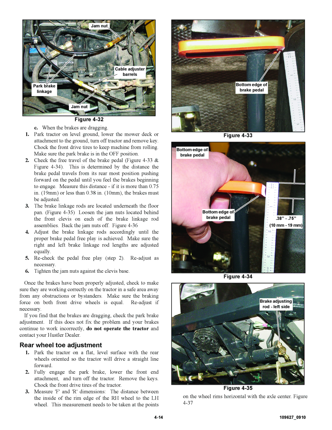
2.Check the free travel of the brake pedal (Figure
3.The brake linkage rods are located underneath the floor pan. (Figure
4.Adjust the brake linkage rods accordingly until the proper brake pedal free play is achieved. Make sure the right and left brake linkage rod lengths are adjusted equally.
5.
6.Tighten the jam nuts against the clevis base.
Once the brakes have been properly adjusted, check to make sure they are working correctly on the tractor in a safe area away from any obstructions or bystanders. Make sure the braking force on both front drive wheels is equal.
If you find that the brakes are dragging, check the park brake adjustment. If this does not fix the problem and your brakes continue to work incorrectly, do not operate the tractor and contact your Hustler Dealer.
Rear wheel toe adjustment
1.Park the tractor on a flat, level surface with the rear wheels oriented so the tractor will drive a straight line forward.
2.Fully engage the park brake, lower the front end attachment, and turn off the tractor. Remove the keys. Chock the front drive tires of the tractor.
3.Measure 'F' and 'R' dimensions: The distance between the inside of the rim edge of the RH wheel to the LH wheel. This measurement needs to be taken at the points
Bottom edge of brake pedal
Figure |
|
Bottom edge of |
|
brake pedal |
|
Bottom edge of |
|
brake pedal | .38” |
| (10 mm - 19 mm) |
Figure |
|
Brake adjusting rod - left side
Figure
on the wheel rims horizontal with the axle center. Figure
