User’s Guide
48X-20X Internal IDE CD-ROM Drive
First Edition September
Contents
iv 48X-20X Internal IDE CD-ROM Drive User’s Guide
About this book
Part 1 Installation and user’s guide
Registering your option
Part 2 Appendixes
vi 48X-20X Internal IDE CD-ROM Drive User’s Guide
Safety information
Läs säkerhetsinformationen innan du installerar den här produkten
Pred inštaláciou tohto zariadenia si pečítaje Bezpečnostné predpisy
Antes de instalar este produto, leia as Informações sobre Segurança
Antes de instalar este producto lea la información de seguridad
Product description
Part 1 Installation and user’s guide
Before you begin
Handling instructions
System requirements
Front view of the drive
Back view of the drive
Reserved
Step 1. Opening the computer
Installing the drive
Step 2. Unpacking the drive
Step 3. Selecting the IDE port
Step 5. Mounting the drive in the bay
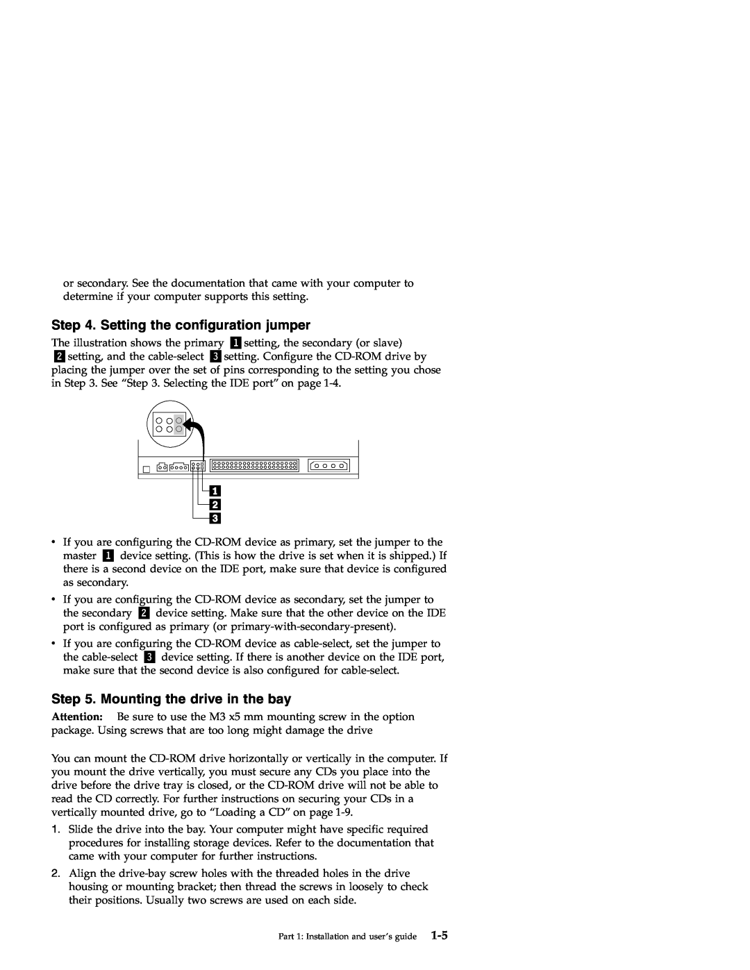
Step 4. Setting the configuration jumper
Step 6. Attaching the cables to the drive
Step 7. Completing the hardware installation
Step 9. Installing device drivers
Step 8. Updating your computer configuration
Caring for a CD
Use and care of the drive
Caring for the CD-ROM drive
Loading a CD
To load a CD into a vertically mounted CD-ROM drive do the following
Manually ejecting a CD
Using a data CD
Playing an audio CD
Windows 95, Windows 98, Windows NT 4.0, Windows 2000, or Windows Me
3. Double-click My Computer
Description du produit
Chapitre 1 Installation et utilisation
1-13
Avant de commencer
Configuration système requise
Vue de la face avant de lunité
Précautions de manipulation
1-15
Vue de la face arrière de lunité
Installation de lunité
Etape 1. Ouverture de lordinateur
«1¬Réservé
Etape 3. Sélection du port IDE
Etape 2. Déballage de lunité
1-17
1-18 48X-20X Internal IDE CD-ROM Drive Users Guide
Etape 4. Positionnement du cavalier de configuration
1-19
Etape 5. Montage de lunité dans la baie
Etape 6. Raccordement des câbles à lunité
Etape 7. Achèvement de linstallation matérielle
Etape 9. Installation des pilotes de périphérique
Etape 8. Mise à jour de la configuration de votre ordinateur
1-21
Manipulation des CD
Précautions dutilisation
Précautions dutilisation de lunité de CD-ROM
1-23
Chargement dun CD
1-24 48X-20X Internal IDE CD-ROM Drive Users Guide
Lecture dun CD audio
Ejection manuelle dun CD
Windows 95, Windows 98, Windows NT 4.0, Windows 2000 ou Windows Me
1-25
1-26 48X-20X Internal IDE CD-ROM Drive Users Guide
Utilisation dun CD de données
Descripción del producto
Parte 1 Instalación y guía del usuario
Antes de empezar
1-27
Instrucciones de manipulación
Requisitos del sistema
Vista frontal de la unidad
Vista posterior de la unidad
1-29
«1¬Reservado
Paso 1. Apertura del sistema
Instalación de la unidad
Paso 2. Desembalaje de la unidad
Paso 3. Selección del puerto IDE
Paso 5. Montaje de la unidad en la bahía
Paso 4. Definición del puente de configuración
1-31
Paso 6. Conexión de los cables a la unidad
Paso 7. Finalización de la instalación del hardware
Paso 8. Actualización de la configuración del sistema
Paso 9. Instalación de los controladores de dispositivos
1-33
Cuidado de un CD
Utilización y cuidado de la unidad
Cuidado de la unidad de CD ROM
1-35
Carga de un CD
1-36 Unidad de CD ROM IDE interna 48X-20X Guía del usuario
Reproducción de un CD de audio
Expulsión de un CD manualmente
Windows 95, Windows 98, Windows NT 4.0, Windows 2000 o Windows Me
Utilización de un CD de datos
1-38 Unidad de CD ROM IDE interna 48X-20X Guía del usuario
Descrizione del prodotto
Parte 1 Guida per lutente e allinstallazione
Prima di iniziare
1-39
Gestione delle istruzioni
Requisiti del sistema
Vista anteriore dellunità
Vista posteriore dellunità
1-41
«1¬Riservato
Passo 1. Apertura dellelaboratore
Installazione dellunità
Passo 2. Disimballaggio dellunità
Passo 3. Selezionare la porta IDE
Passo 5. Fissaggio dellunità nel vano
Passo 4. Impostazione del cavallotto di configurazione
1-43
Passo 6. Collegamento dei cavi allunità
Passo 8. Aggiornamento della configurazione dellelaboratore
Passo 7. Completamento dellinstallazione dellhardware
Passo 9. Installazione dei driver di periferica
1-45
1-46 Unità CD-ROM con IDE interno 48X-20X Guida per lutente
Manutenzione di un CD
Utilizzo e manutenzione dellunità
Manutenzione dellunità CD-ROM
1-47
Caricamento di un CD
1. Premere il pulsante di espulsione/caricamento
1-49
Riproduzione di un CD audio
Espulsione manuale di un CD
Utilizzo di un CD dati
1. Accendere lelaboratore ed avviare il sistema operativo
1-51
1-52 Unità CD-ROM con IDE interno 48X-20X Guida per lutente
Descrição do Produto
Parte 1 Instalação e Guia do Usuário
Antes de Começar
1-53
Instruções de Manuseio
Requisitos do Sistema
Vista Frontal da Unidade
Vista Posterior da Unidade
Etapa 1. Abrindo o Computador
Instalando a Unidade
Etapa 2. Desembalando a Unidade
Etapa 3. Selecionando a Porta IDE
Etapa 4. Definindo o Jumper de Configuração
1-58 Unidade de Disco de CD-ROM IDE Interna 48X-20X Guia do Usuário
Etapa 5. Montando a Unidade no Compartimento
Etapa 6. Conectando os Cabos à Unidade
Step 8. Atualizando a Configuração do Computador
Etapa 7. Concluindo a Instalação do Hardware
1-60 Unidade de Disco de CD-ROM IDE Interna 48X-20X Guia do Usuário
Etapa 9. Instalando Drivers de Dispositivo
Cuidando de um CD
Utilização e Cuidados com a Unidade
Cuidados com a Unidade de CD-ROM
Carregando um CD
1. Pressione o botão Ejetar/Carregar
Reproduzindo um CD de Áudio
Ejetando Manualmente um CD
Utilizando um CD de Dados
3. Dê um clique duplo em Meu Computador
1-66 Unidade de Disco de CD-ROM IDE Interna 48X-20X Guia do Usuário
1 í≈Gw ΓU
1-67
hB BzN
Page
BJ 2. ε
BJ 1. qú
BJ 3. ∩
IDE s ≡
BJ 5. N ≈w ≈ñ
BJ 7. ¿wΘw @
BJ 6. s u
BJ 8. ≤sqútm
1-72 48X-20X í IDE ≈ ΓU
Windows 95BWindows 98BWindows NTBWindows
BJ 9. w ≈
Windows Me
≈ POi
Page
1-76 48X-20X í IDE ≈ ΓU
2000
Windows 95BWindows 98BWindows NT 4.0BWindows
Windows Me
y ²C. Help and service informationz Ñσ
B. Problem solvingz C-1
6. d TziH W C
pGzLk∩ CD-ROM
Oak0K
=Jb@
1-79
QH 1 $s9Hk*hSf6&,$I
hj7$eNb@
79F`Wo
\Ii$VN5L
\Ii$VNXL
9FCW 1. 3sTe?r+
\Ii$VNhjU1
9FCW 2. Ii$Vr-q+ihjP9
9FCW 3. IDE Hr*r9k
9FCW 5. \Ii$VrY$KhjU1k
9FCW 4. =.8csQrj9k
9FCW 7. OI&NhjU1r09k
9FCW 6. 1Vkr\Ii$VK\39k
9FCW 9. GP$9&Ii$Pr$s9Hk9k
9FCW 8. 3sTe?N=.r979k
Windows 95Windows 98Windows NTWindows 2000*hS
Windows Me QNGP$9&Ii$P
CD Nj~l
Ii$VNHQHj~l
CD-ROM Ii$VNj~l
± b9bY?OMw ± aYN60cJWb?O9$?L ± aYN3j
CD NCH
#KhjU1il? CD-ROM Ii$VK CD rCH9kKO!Nh&K 7F/@5$#
1. $8/H/CH&\?sr!79#Hl$,Ii$V+i9i$I7F PF-9#
2. r+F*H$N CD Hl$HfS7F/@5$#
DKhjU1il? CD-ROM Ii$VK CD rCH9kKO!Nh&K 7F/@5$# 1. $8/H/CH&\?sr!79#
v *H$N CD Hl$,&NKwF$klgO CD rHl$K~ 7\0D=J?Vr0K=CH!7F CD rjjNLVK7 9#
3. $8/H/CH&\?sr!9+Hl$r=CH!7~lFCD Hl $rD89#
G#* CD NF8
CD rj0GhjP9
Windows 95Windows 98Windows NT 4.0Windows 2000?O Windows Me
G? CD NHQ
1-90 48X-20X Internal IDE CD-ROM Drive Users Guide
Changing the Windows 98 and Windows Me device-driver settings
Appendix A. Customizing device driver configuration settings
1. Click Start--Settings--Control Panel
Changing the Windows 2000 desktop device driver
7. Click the Advanced Settings tab
Problem descriptions
Appendix B. Problem solving
To verify that the icon is there do the following
b. Click Properties
1. Click Start -- Settings -- Control Panel
Appendix B. Problem solving
The CD does not play sound
The CD cannot be read
B-4 48X-20X Internal IDE CD-ROM Drive User’s Guide
v CDR-101
You receive a common error message
2. Select Properties
v CDR-103
Online technical support
Appendix C. Help and service information
Telephone technical support
Canada Toronto only
Support 24 hours a day, 7 days a week
Canada all other
U.S.A. and Puerto Rico
The IBM Warranty for Machines
Warranty Statements
Appendix D. Product warranties and notices
Items Not Covered by Warranty
Extent of Warranty
WARRANTIES OF ANY KIND
OF ANY KIND
Warranty Service
Limitation of Liability
Production Status
D-4 48X-20X Internal IDE CD-ROM Drive User’s Guide
Extent of Warranty
D-6 48X-20X Internal IDE CD-ROM Drive User’s Guide
OF ANY KIND Warranty Service
Limitation of Liability
Part 2 - Worldwide Country-Unique Terms
AUSTRALIA The IBM Warranty for Machines The following paragraph is
ASIA PACIFIC
D-8 48X-20X Internal IDE CD-ROM Drive User’s Guide
PEOPLE’S REPUBLIC OF CHINA Governing Law The following is added to
NEW ZEALAND The IBM Warranty for Machines The following paragraph
EUROPE, MIDDLE EAST, AFRICA EMEA
The following terms apply to all EMEA countries
The following terms apply to the country specified
D-11
NORTH AMERICA
UNITED STATES OF AMERICA Warranty Service The following is added to
D-12 48X-20X Internal IDE CD-ROM Drive User’s Guide
D-13
Notices
Trademarks
Tested To Comply With FCC Standards FOR HOME OR OFFICE USE
Federal Communications Commission FCC statement
D-15
48X-20X CD-ROM Drive
Avis de conformite a la reglementation d’Industrie Canada
Industry Canada Class B emission compliance statement
Deutsche EMV-Direktive electromagnetische Verträglichkeit
European Union - emission directive
Unione Europea - Directiva EMC Conformidad électromagnética
D-17
Union Europea - Normativa EMC
D-18 48X-20X Internal IDE CD-ROM Drive User’s Guide
Page
Part Number 71P7279
71P7279