Analog output
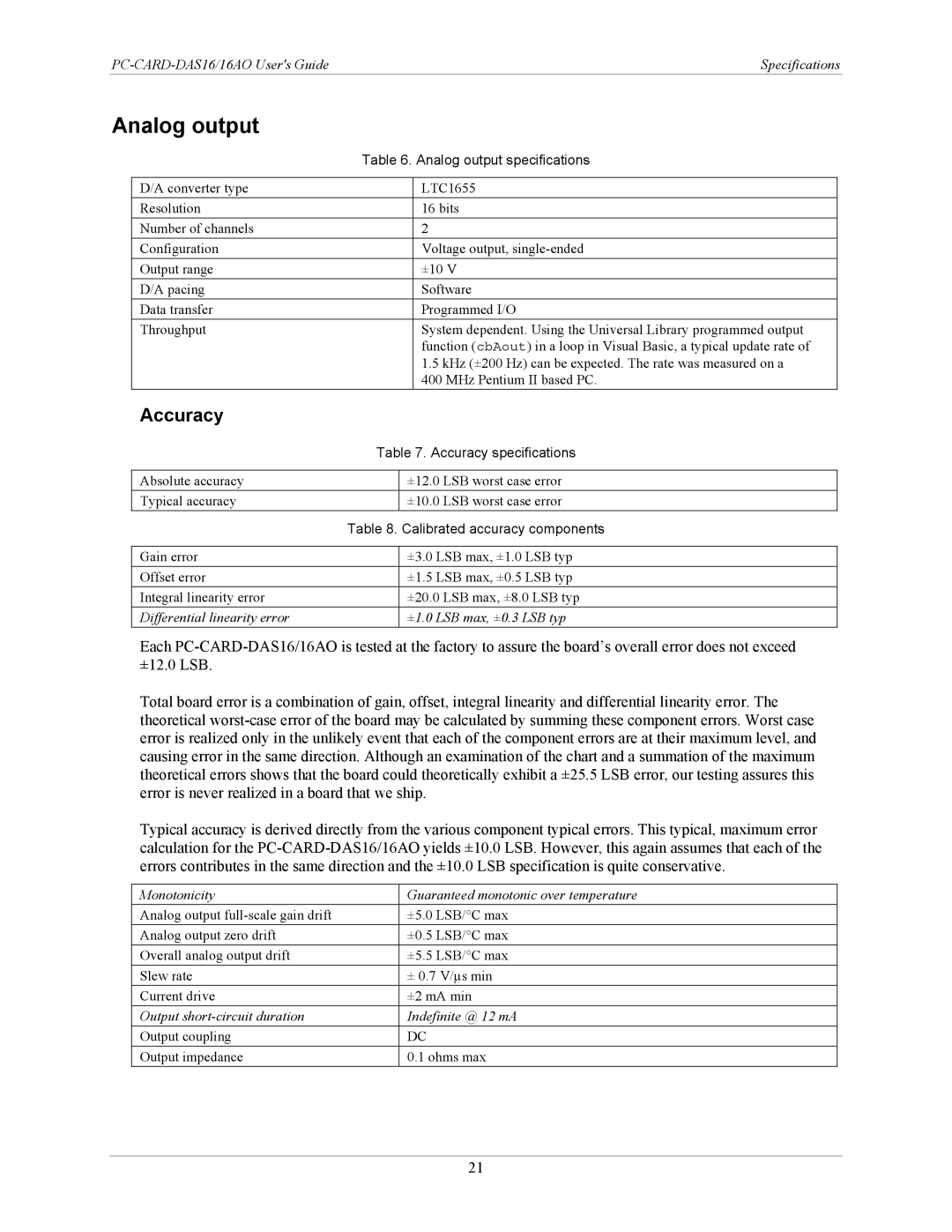
| Table 6. Analog output specifications | ||
|
|
|
|
D/A converter type |
|
| LTC1655 |
Resolution |
|
| 16 bits |
Number of channels |
|
| 2 |
Configuration |
|
| Voltage output, |
Output range |
|
| ±10 V |
D/A pacing |
|
| Software |
Data transfer |
|
| Programmed I/O |
Throughput |
|
| System dependent. Using the Universal Library programmed output |
|
|
| function (cbAout) in a loop in Visual Basic, a typical update rate of |
|
|
| 1.5 kHz (±200 Hz) can be expected. The rate was measured on a |
|
|
| 400 MHz Pentium II based PC. |
Accuracy |
|
|
|
| Table 7. Accuracy specifications | ||
|
|
| |
Absolute accuracy |
| ±12.0 LSB worst case error | |
Typical accuracy |
| ±10.0 LSB worst case error | |
| Table 8. Calibrated accuracy components | ||
|
|
| |
Gain error |
| ±3.0 LSB max, ±1.0 LSB typ | |
Offset error |
| ±1.5 LSB max, ±0.5 LSB typ | |
Integral linearity error |
| ±20.0 LSB max, ±8.0 LSB typ | |
Differential linearity error |
| ±1.0 LSB max, ±0.3 LSB typ | |
Each
Total board error is a combination of gain, offset, integral linearity and differential linearity error. The theoretical
Typical accuracy is derived directly from the various component typical errors. This typical, maximum error calculation for the
Monotonicity | Guaranteed monotonic over temperature |
Analog output | ±5.0 LSB/°C max |
Analog output zero drift | ±0.5 LSB/°C max |
Overall analog output drift | ±5.5 LSB/°C max |
Slew rate | ± 0.7 V/µs min |
Current drive | ±2 mA min |
Output | Indefinite @ 12 mA |
Output coupling | DC |
Output impedance | 0.1 ohms max |
21