InstallationEP-8KTA
AUX1: Auxiliary Line_IN Connector
• Pin1(Left Line_IN), Pin2/Pin3(GND), Pin4(Right
MODEM1: Telephony Connector
• Pin1(Audio_in), Pin2/Pin3(GND),
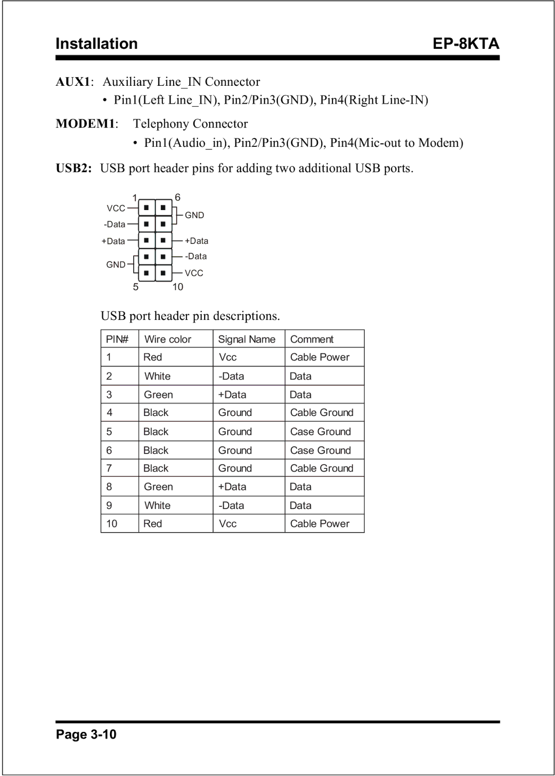
USB2: USB port header pins for adding two additional USB ports.
1 |
|
|
| 6 |
|
| ||||
|
|
| ||||||||
VCC |
|
|
|
|
|
|
|
| GND | |
|
|
|
|
|
|
|
| |||
|
|
|
|
|
|
|
|
| ||
|
|
|
|
|
|
|
|
| ||
+Data |
|
|
|
|
|
|
|
|
| +Data |
GND |
|
|
|
|
|
|
|
|
| |
|
|
|
|
|
|
|
|
| ||
|
|
|
|
|
|
|
|
| ||
|
|
|
|
|
|
|
|
| VCC | |
|
|
|
|
|
|
|
|
| ||
|
|
|
|
|
|
|
|
|
|
|
510
USB port header pin descriptions.
PIN# | Wire color | Signal Name | Comment |
|
|
|
|
1 | Red | Vcc | Cable Power |
|
|
|
|
2 | White | Data | |
|
|
|
|
3 | Green | +Data | Data |
|
|
|
|
4 | Black | Ground | Cable Ground |
|
|
|
|
5 | Black | Ground | Case Ground |
|
|
|
|
6 | Black | Ground | Case Ground |
|
|
|
|
7 | Black | Ground | Cable Ground |
|
|
|
|
8 | Green | +Data | Data |
|
|
|
|
9 | White | Data | |
|
|
|
|
10 | Red | Vcc | Cable Power |
|
|
|
|
Page
