RS/6000 SP specifications
The IBM RS/6000 SP (Scalable Power) is a high-performance computing system that was developed in the early 1990s and has since become a significant player in the realm of supercomputing and enterprise solutions. Designed primarily for scientific, engineering, and complex data analysis tasks, the RS/6000 SP provides powerful processing capabilities, enhanced scalability, and features to support demanding applications.One of the key characteristics of the RS/6000 SP is its modular architecture, which allows for the addition of multiple nodes. Each node is based on IBM's Power architecture, leveraging the RISC (Reduced Instruction Set Computing) design to achieve high throughput and efficiency. The system can support configurations ranging from a few nodes to hundreds, enabling organizations to scale their computational power as needed based on workload requirements.
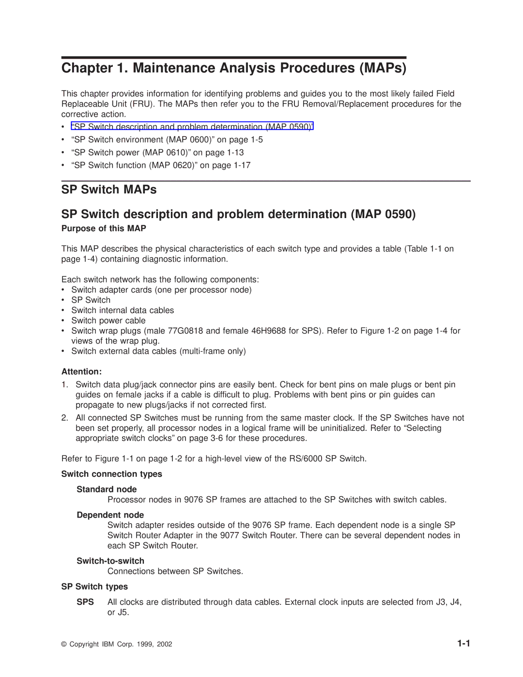
The RS/6000 SP employs advanced interconnect technologies, most notably the SP Switch, which ensures high-speed communication between nodes. This interconnect allows for seamless data transfer, ensuring that the system can handle large datasets and complex computations without bottlenecks. The SP's ability to deliver concurrent processing capabilities makes it ideal for parallel computing tasks, including simulations, modeling, and large-scale computations.
In terms of software, the RS/6000 SP was equipped with AIX, IBM's version of the UNIX operating system, which provides a stable and secure environment for enterprise applications. Furthermore, the system supports a vast array of programming languages and tools, including Fortran, C, and C++, along with libraries and frameworks designed for high-performance computing. This compatibility allows developers to optimize their applications to fully utilize the underlying hardware.
Another notable feature of the RS/6000 SP is its extensive support for various workloads, including database management, multi-user applications, and graphical processing. The system was equipped with high-performance graphics capabilities, making it suitable for tasks that require intensive visualization, such as computer-aided design (CAD) and scientific visualization.
Overall, the IBM RS/6000 SP has solidified its role in the high-performance computing landscape, combining advanced technologies, robust scalability, and flexibility to meet the unique demands of research and enterprise environments. Its legacy continues to influence modern computing architectures, embodying IBM’s commitment to innovation and performance in the pursuit of complex problem-solving capabilities.

