ICE Series | Electrical System |
Untimed Freeze Cycle
During the freeze cycle the compressor, water pump and condenser fan motor(s) (if used) are running. On remote systems the liquid line solenoid is also energized, see Refrigeration System. As ice forms on the evaporator, the suction pressure drops. The machine is in the untimed portion of the freeze cycle and will remain in untimed freeze until the suction pressure drops low enough to close the timer initiate control. See page
Timer Initiate
The timer initiate is a
The timer initiate is factory set and does not normally need to be adjusted. If the ice bridge thickness is incorrect, the freeze timer should be adjusted rather than the timer initiate. See page F4 for freeze timer adjustment procedure. The timer initiate may need to be adjusted if excessive time (more than 7 minutes) is needed on the timer to achieve proper bridge thickness of if very little time (less than 1 minute) is needed on the timer to achieve proper bridge thickness.
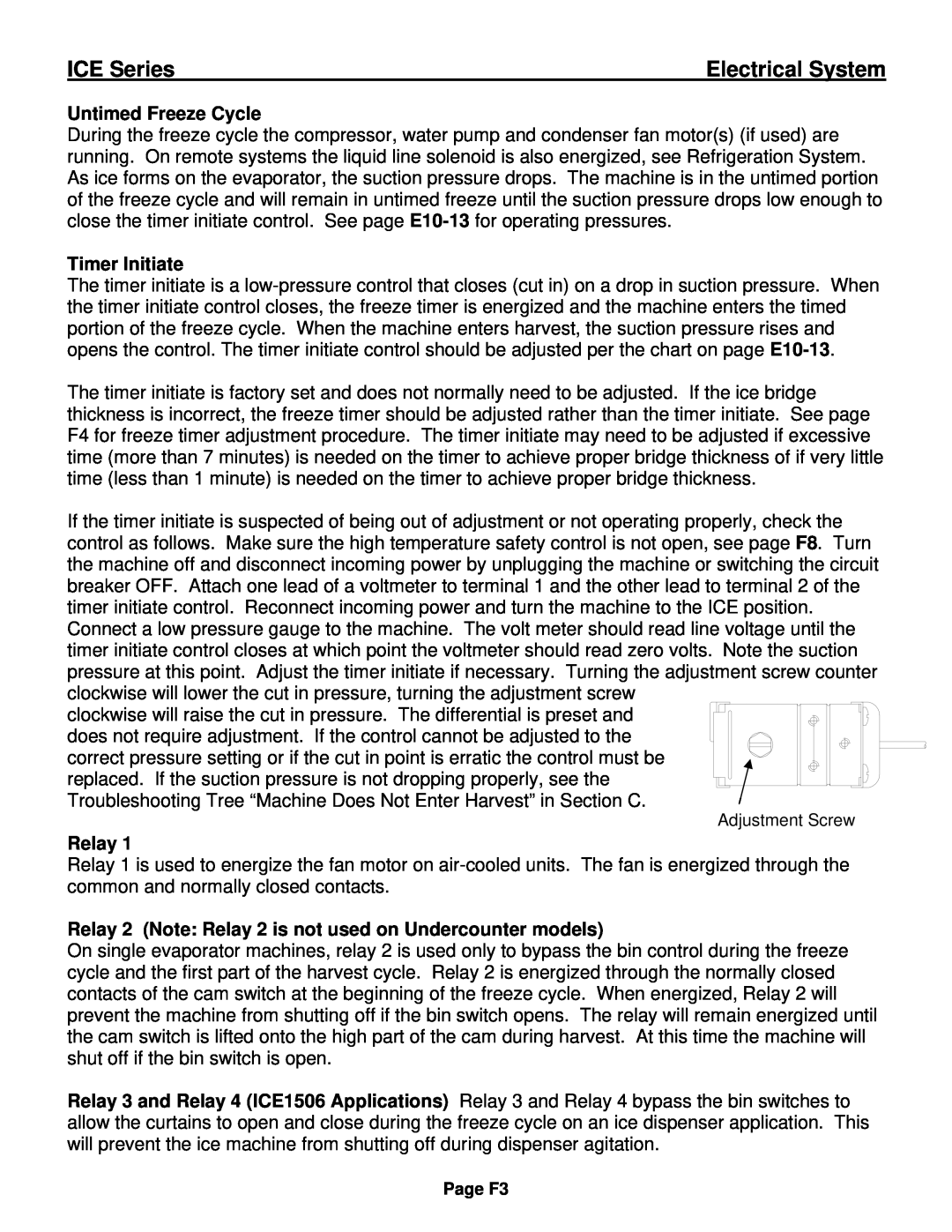
If the timer initiate is suspected of being out of adjustment or not operating properly, check the control as follows. Make sure the high temperature safety control is not open, see page F8. Turn the machine off and disconnect incoming power by unplugging the machine or switching the circuit breaker OFF. Attach one lead of a voltmeter to terminal 1 and the other lead to terminal 2 of the timer initiate control. Reconnect incoming power and turn the machine to the ICE position. Connect a low pressure gauge to the machine. The volt meter should read line voltage until the timer initiate control closes at which point the voltmeter should read zero volts. Note the suction pressure at this point. Adjust the timer initiate if necessary. Turning the adjustment screw counter clockwise will lower the cut in pressure, turning the adjustment screw
clockwise will raise the cut in pressure. The differential is preset and does not require adjustment. If the control cannot be adjusted to the
correct pressure setting or if the cut in point is erratic the control must be replaced. If the suction pressure is not dropping properly, see the Troubleshooting Tree “Machine Does Not Enter Harvest” in Section C.
Adjustment Screw
Relay 1
Relay 1 is used to energize the fan motor on
Relay 2 (Note: Relay 2 is not used on Undercounter models)
On single evaporator machines, relay 2 is used only to bypass the bin control during the freeze cycle and the first part of the harvest cycle. Relay 2 is energized through the normally closed contacts of the cam switch at the beginning of the freeze cycle. When energized, Relay 2 will prevent the machine from shutting off if the bin switch opens. The relay will remain energized until the cam switch is lifted onto the high part of the cam during harvest. At this time the machine will shut off if the bin switch is open.
Relay 3 and Relay 4 (ICE1506 Applications) Relay 3 and Relay 4 bypass the bin switches to allow the curtains to open and close during the freeze cycle on an ice dispenser application. This will prevent the ice machine from shutting off during dispenser agitation.
Page F3