SERVICE AND INSTALLATION MANUAL THE ICE SERIES CUBERS
Includes Undercounter and 22 Inch Series
ICE0250 through ICE2100 SERIES
ICE Series
Table Of Contents
Table of Contents
Table of Contents
Scheduled Maintenance
Ice-O-Matic products are not designed for outdoor installation
How To Use This Manual
General Information
Keep this manual for future reference
Serial Number Date Code
Model and Serial Number Format Model Numbers ICE 040 0 H A
Reference new serial number format on next page
ICE Series
ICE Series
Model and Serial Number Format
General Information
General Information
ICE Series
Page A5
Model
General Information
ICE Series
Page A6
Model
General Information
ICE Series
Model
BTUH
General Information
ICE Series
50 hz
@ 90/70
Ambient Operating Temperatures
Installation Guidelines
Note Ice-O-Matic products are not designed for outdoor installation
Adjustments
General Information
ICE Series
Page A10
ICE Series
Electrical and Plumbing Requirements ICEU150, 220, 225 and
General Information
Page A11
ICE Series
Electrical and Plumbing Requirements ICEU300 and
General Information
Page A12
General Information
ICE Series
Page A13
General Information
ICE Series
Page A14
General Information
ICE Series
Page A15
General Information
ICE Series
Page A16
ICE Series
Electrical and Plumbing Requirements ICE1506 Remote
General Information
Page A17
Installation Guidelines
Remote Condenser Installation
Air Flow
ICE Series
General Information
ICE Series
ICE Machine Model Number
ICE Series
How the ICE Machine Works
General Information
Page A20
ICE Series
Undercounter Bin Removal-ICEU300 Series
General Information
The storage bin can be removed by 1 Remove the lower grill
ICE Series
Undercounter Bin Removal-ICEU150/200 Series
General Information
Page A22
Water Filtration System Extended Warranty Program
Warranty Information
PARTS
LABOR
ICE Series
Ice-O-Matic Parts and Labor Domestic & International Limited Warranty
General Information
Page A24
Maintenance
Scheduled Maintenance
Maintenance Procedure
Cleaning and Sanitizing
Scheduled Maintenance
Cleaning and Sanitizing continued
ICE Series
Winterizing Procedures
Winterizing Procedures
ICE Series
Cleaning Activity
Cleaning stainless steel
Cleaning Agent
Cabinet Care
How To Use The Troubleshooting Trees
Troubleshooting Trees
ICE Series
Troubleshooting Trees
Troubleshooting Trees Table Of Contents
ICE Series
Troubleshooting Trees
Machine Does Not Run
ICE Series
ICE ?
Troubleshooting Trees
Machine Runs, Does Not Make Ice
ICE Series
YES YES OK HIGH OK
Troubleshooting Trees
Machine Runs, Does Not Make Ice continued
ICE Series
HIGH OR NORMAL
Troubleshooting Trees
Slow Production Cube Formation Good
ICE Series
TOO HIGH
Troubleshooting Trees
Low Suction Pressure
ICE Series
NOT OK DRY SYSTEM
Troubleshooting Trees
High Suction Pressure
ICE Series
NOT OK
Troubleshooting Trees
Cubes Are Hollow
ICE Series
Page C9
Troubleshooting Trees
Uneven Bridge Thickness
ICE Series
Page C10
Troubleshooting Trees
Ice bridge Thickness Varies Cycle To Cycle
ICE Series
Check the Purge
Troubleshooting Trees
Machine Produces Cloudy Ice
ICE Series
Page C12
Troubleshooting Trees
Poor Water Distribution Over The Evaporator
ICE Series
OBSTRUCTED
Troubleshooting Trees
Machine Does Not Enter Harvest
ICE Series
NO OK
Troubleshooting Trees
Machine Enters Harvest, Then Returns To Freeze Prematurely
ICE Series
OPEN
Troubleshooting Trees
Length Of Harvest Excessive
ICE Series
NOT OK
Troubleshooting Trees
Ice Does Not Release From Evaporator
ICE Series
NOT OK
Troubleshooting Trees
Hot Evaporator, Low Suction And Discharge Pressure Remote Only
ICE Series
Page C18
Water Distribution and Components
Water System
Float Valve
ICE Series
Water Distribution Tube
Water Distribution Disassembly
ICE Series
Water System
ICE Series
Water Splash Curtain
Water System
ICE Series
Water Purge Valve
Water System
ICEU150/200 Models
Water Trough
ICE 30 Inch Wide Models
ICE 22 Inch Wide Models
Refrigerant Cycle and Components
Refrigeration System
Refrigerant Pressures
Compressor
Method of Charging Refrigerant
Refrigerant
ICE Series
Refrigeration System
Problem
Symptom
ICE SeriesRefrigeration System
Thermostatic Expansion Valve TXV
Evaporator
Thermostatic Expansion Valve Continued
ICE Series
Refrigeration System
Hot Gas Valve
Harvest Cycle
Remote System
Remote Condenser
Mixing Valve
Remote Condenser Continued
Possible Cause
Remedy
Liquid Line Solenoid
Pump Down System Remote Only
Receiver
ICE Series
Refrigeration System
ICE Series
Refrigerant
Method of Charging Refrigerant
Refrigeration System
ICE Series
Reference Tables on Page E10 and E13
Refrigeration System
ICE Series
Back
Batch
Refrigeration System
ICE Series
Back
Batch
Refrigeration System
ICE Series
Back
Batch
Refrigeration System
ICE Series
Charge
Model
ICE Series
Refrigeration System
Page E14
Refrigeration System
ICE Series
Page E15
Refrigeration System
ICE Series
Page E16
Refrigeration System
ICE Series
Page E17
Refrigeration System
ICE Series
Page E18
Refrigeration System
ICE Series
Page E19
Refrigeration System
ICE Series
Page E20
Purge Switch
Selector Switch
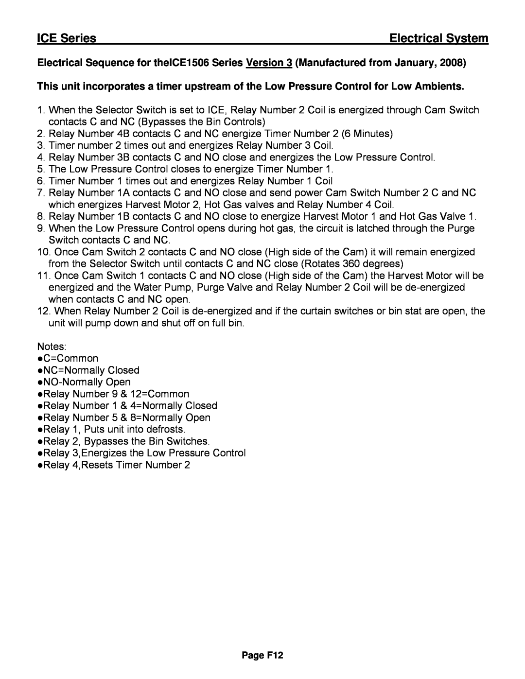
Electrical System
Control Circuit
Overload External
Compressor Check Continued
Capacitors
Start Relay
Untimed Freeze Cycle
Timer Initiate
Relay
Relay 2 Note Relay 2 is not used on Undercounter models
Timed Freeze
Freeze Timer
ICE Series
Electrical System
Dual Evaporator Machines
Harvest Cycle Single Evaporator Machines
ICE Series
Electrical System
Harvest Motor
Clutch Assembly
ICE Series
Electrical System
Cam Switch Operation-Dual Evaporator Machines Prior to January
Cam Switch Operation-Single Evaporator Machines
Probe Tip and Swivel
ICE Series
not covered under warranty
Cam Switch Adjustment
Bin Control Operation
ICE Series
Adjustments are not covered under warranty Undercounter Models
Bin Control Adjustment
Pump Down Control
Fan Control
Electrical System
ICE Series
2. The LP Control energizes Relay Number 2 Coil
Electrical System
ICE Series
Page F11
Electrical System
ICE Series
Page F12
ICEU150/200/205/206 Air and Water Wiring Diagram
Wiring Diagram
ICE Series
Wiring Diagram
ICEU150/200/205/206 Air and Water Wiring Schematic
ICE Series
Page G2
Wiring Diagram
ICEU150/220/225/226 Air and Water Wiring Diagram
ICE Series
Page G3
Wiring Diagram
ICEU150/220/225/226 Air and Water Wiring Schematic
ICE Series
Page G4
Wiring Diagram
ICE0250 Air and Water Wiring Diagram
ICE Series
Page G5
Wiring Diagram
ICE0250 Air and Water Wiring Schematic
ICE Series
Page G6
Wiring Diagram
ICE0400 Air and Water Wiring Diagram
ICE Series
Page G7
Wiring Diagram
ICE0400 Air and Water Wiring Schematic
ICE Series
Page G8
Wiring Diagram
ICE0405/0406 Air and Water Wiring Diagram
ICE Series
Page G9
Wiring Diagram
ICE0405/0406 Air and Water Wiring Schematic
ICE Series
Page G10
Wiring Diagram
ICE0500 Air and Water Wiring Diagram
ICE Series
Page G11
Wiring Diagram
ICE0500 Air and Water Wiring Schematic
ICE Series
Page G12
Wiring Diagram
ICE0500 Remote Wiring Diagram
ICE Series
Page G13
Wiring Diagram
ICE0500 Remote Wiring Schematic
ICE Series
Page G14
Wiring Diagram
ICE0605/0606/0805/0806/1005/1006 Air and Water Wiring Diagram
ICE Series
Page G15
Wiring Diagram
ICE0605/0606/0805/0806/1005/1006 Air and Water Wiring Schematic
ICE Series
Page G16
Wiring Diagram
ICE0605/0606/0805/0806/1005/1006 Remote Wiring Diagram
ICE Series
Page G17
Wiring Diagram
ICE0605/0606/0805/0806/1005/1006 Remote Wiring Schematic
ICE Series
Page G18
Wiring Diagram
ICE1007 Air and Water Wiring Diagram
ICE Series
Page G19
Wiring Diagram
ICE1007 Air and Water Wiring Schematic
ICE Series
Page G20
Wiring Diagram
ICE1007 Remote Wiring Diagram
ICE Series
Page G21
Wiring Diagram
ICE1007 Remote Wiring Schematic
ICE Series
Page G22
Wiring Diagram
ICE1405/1406/1806/2005/2106 Air and Water Wiring Diagram
ICE Series
Page G23
Wiring Diagram
ICE1405/1406/1806/2005/2106 Air and Water Wiring Schematic
ICE Series
Page G24
Wiring Diagram
ICE1405/1406/1806/2005/2106 Remote Wiring Diagram
ICE Series
Page G25
Wiring Diagram
ICE1405/1406/1806/2005/2106 Remote Wiring Schematic
ICE Series
Page G26
Wiring Diagram
ICE1407/1807/2107 Air and Water Wiring Diagram
ICE Series
Page G27
Wiring Diagram
ICE1407/1807/2107 Air and Water Wiring Schematic
ICE Series
Page G28
Wiring Diagram
ICE1407/1807/2107 Remote Wiring Diagram
ICE Series
Page G29
Wiring Diagram
ICE1407/1807/2107 Remote Wiring Schematic
ICE Series
Page G30
Wiring Diagram
ICE1606 Remote Wiring Diagram
ICE Series
Page G31
Wiring Diagram
ICE1606 Remote Wiring Schematic
ICE Series
Page G32
Wiring Diagram
ICE0320 Air and Water Wiring Diagram
ICE Series
Page G33
Wiring Diagram
ICE0320 Air and Water Wiring Schematic
ICE Series
Page G34
Wiring Diagram
ICE0520 Air and Water Wiring Diagram
ICE Series
Page G35
Wiring Diagram
ICE0520 Air and Water Wiring Schematic
ICE Series
Page G36
Wiring Diagram
ICE0325/0525 Air and Water Wiring Diagram
ICE Series
Page G37
Wiring Diagram
ICE0325/0525 Air and Water Wiring Schematic
ICE Series
Page G38
Wiring Diagram
ICE0305 Air and Water Wiring Diagram
ICE Series
Page G39
Wiring Diagram
ICE0305 Air and Water Wiring Schematic
ICE Series
Page G40
Wiring Diagram
ICE1506 Remote
ICE Series
Page G41
ICE Series
Wiring Diagram
ICE1506 Remote
Page G42
Wiring Diagram
ICEU300 Air and Water
ICE Series
Page G43
ICE Series
Wiring Diagram
ICEU300 Air and Water
Page G44
Wiring Diagram
ICEU305 Air and Water
ICE Series
Page G45
ICE Series
Wiring Diagram
ICEU305 Air and Water
Page G46
Wiring Diagram
ICE0500 Remote Wiring Diagram R3
ICE Series
Page G47
Wiring Diagram
ICE0500 Remote Wiring Schematic R3
ICE Series
Page G48
Wiring Diagram
ICE0605/0606/0806/1006 Remote Wiring Diagram R3
ICE Series
Page G49
Wiring Diagram
ICE0605/0606/0806/1006 Remote Wiring Schematic R3
ICE Series
Page G50
Wiring Diagram
ICE1007 Remote Wiring Diagram R3
ICE Series
Page G51
Wiring Diagram
ICE1007 Remote Wiring Schematic R3
ICE Series
Page G52
Wiring Diagram
ICE0250 Air4 and Water4, ICE0400 Air3 and Water3 Wiring Diagram
ICE Series
Page G53
Wiring Diagram
ICE0250 Air4 and Water4, ICE0400 Air3 and Water3 Wiring Schematic
ICE Series
Page G54
Wiring Diagram
ICE0320 Air3 and Water3, ICE0520 Air3 and Water3 Wiring Diagram
ICE Series
Page G55
Wiring Diagram
ICE0320 Air4 and Water4, ICE0520 Air3 and Water3 Wiring Schematic
ICE Series
Page G56
Wiring Diagram
ICE0406/405 Air3 and Water3, ICE0305 Air3 and Water3 Wiring Diagram
ICE Series
Page G57
Wiring Diagram
ICE0406/405 Air3 and Water3, ICE0305 Air3 and Water3 Wiring Schematic
ICE Series
Page G58
Wiring Diagram
ICE0325 Air3 and Water3, ICE0525 Air3 and Water3 Wiring Diagram
ICE Series
Page G59
Wiring Diagram
ICE0325 Air3 and Water3, ICE0525 Air3 and Water3 Wiring Schematic
ICE Series
Page G60
Wiring Diagram
ICE0500 Air3 and Water3 Wiring Diagram
ICE Series
Page G61
Wiring Diagram
ICE0500 Air3 and Water3 Wiring Schematic
ICE Series
Page G62
Wiring Diagram
ICE0500 Remote4 Wiring Diagram
ICE Series
Page G63
Wiring Diagram
ICE0500 Remote4 Wiring Schematic
ICE Series
Page G64
Wiring Diagram
ICE0606 Air3 and Water3, ICE0605 Air3 and Water3 Wiring Diagram
ICE Series
Page G65
Wiring Diagram
ICE0606 Air3 and Water3, ICE0605 Air3 and Water3
ICE Series
Page G66
Wiring Diagram
ICE0606 Remote4 and ICE0605 Remote4 Wiring Diagram
ICE Series
Page G67
Wiring Diagram
ICE0606 Remote4 and ICE0605 Remote4 Wiring Schematic
ICE Series
Page G68
ICE0606 Remote4 and ICE0605 Remote4 Wiring Schematic
Wiring Diagram
ICE Series
Wiring Diagram
ICE1405/6A3/W3, ICE1806W3 and ICE2106W3 Wiring Diagram
ICE Series
Page G69
Wiring Diagram
ICE1405/6A3/W3, ICE1806W3 and ICE2106W3 Wiring Schematic
ICE Series
Page G70
Wiring Diagram
ICE1407A3/W3, ICE1807W3 and ICE2107W3 Wiring Diagram
ICE Series
Page G71
Wiring Diagram
ICE1407A3/W3, ICE1807W3 and ICE2107W3 Wiring Schematic
ICE Series
Page G72
Wiring Diagram
ICE1405/6R3, ICE1806R3 and ICE2106R3 Wiring Diagram
ICE Series
Page G73
Wiring Diagram
ICE1405/6R3, ICE1806R3 and ICE2106R3 Wiring Schematic
ICE Series
Page G74
Wiring Diagram
ICE1407R3, ICE1807R3 and ICE2107R3 Wiring Diagram
ICE Series
Page G75
Wiring Diagram
ICE1407R3, ICE1807R3 and ICE2107R3 Wiring Schematic
ICE Series
Page G76
Wiring Diagram
ICE1506R3 Wiring Diagram
ICE Series
Page G77
Wiring Diagram
ICE1506R3 Wiring Schematic
ICE Series
Page G78