6-3 TRANSMIT ADJUSTMENT
Select an adjustment item using [↑] / [↓] keys, then set to the specified value using [←] / [→] keys on the connected PC's keyboard.
ADJUSTMENT | ADJUSTMENT CONDITION |
|
| MEASUREMENT |
|
| VALUE | |||||||
| UNIT | OPERATION |
|
| ||||||||||
|
|
|
|
|
|
|
|
|
|
|
| |||
|
|
|
|
|
|
|
|
|
|
|
|
|
|
|
OUTPUT | 1 | • Channel | : CH 3 |
| Top | Connect an RF power meter to |
|
|
| 5.0 W | ||||
POWER |
| • Transmitting |
|
| panel | the antenna connector. |
|
|
|
|
|
|
| |
[Power (Hi)] |
|
|
|
|
|
|
|
|
|
|
|
|
|
|
|
|
|
|
|
|
|
|
|
|
|
|
|
|
|
[Power (L2)] | 2 | • Channel | : CH 4 |
|
|
|
|
|
|
| 2.0 W | |||
|
| • Transmitting |
|
|
|
|
|
|
|
|
|
|
|
|
|
|
|
|
|
|
|
|
|
|
|
|
|
|
|
[Power (L1)] | 3 | • Channel | : CH 5 |
|
|
|
|
|
|
| 1.0 W | |||
|
| • Transmitting |
|
|
|
|
|
|
|
|
|
|
|
|
|
|
|
|
|
|
|
|
|
|
|
|
|
| |
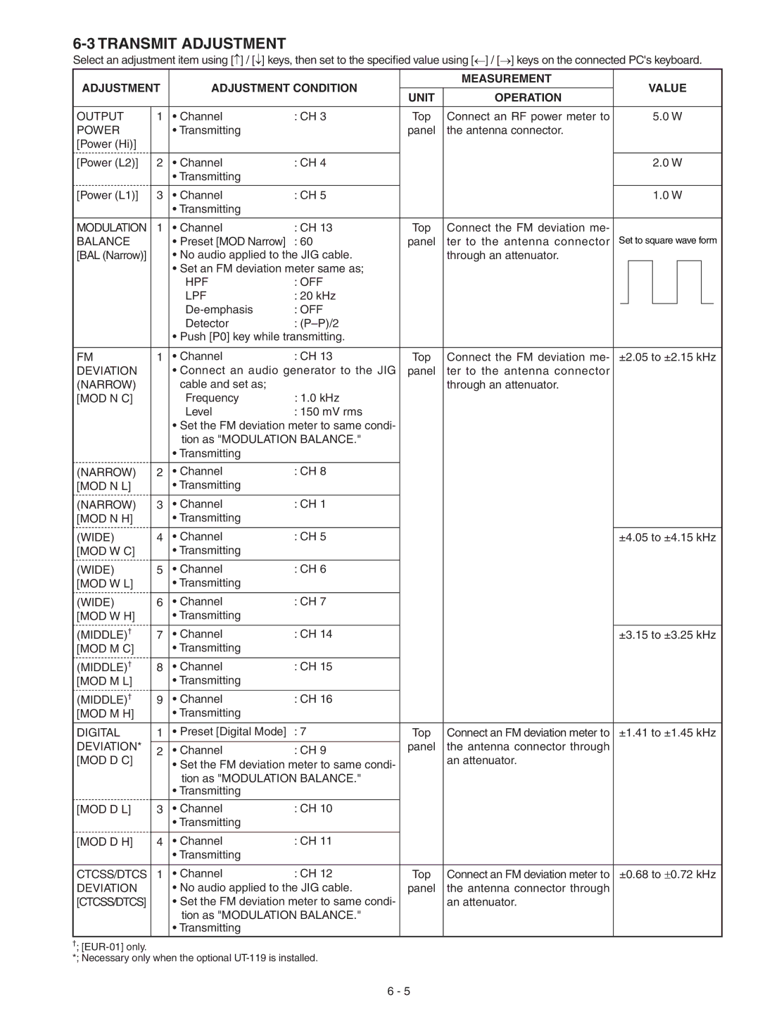
MODULATION | 1 | • Channel | : CH 13 |
| Top | Connect the FM deviation me- |
|
|
|
|
|
|
| |
BALANCE |
| • Preset [MOD Narrow] | : 60 |
| panel | ter to the antenna connector | Set to square wave form | |||||||
[BAL (Narrow)] |
| • No audio applied to the JIG cable. |
|
| through an attenuator. |
|
|
|
|
|
|
| ||
|
| • Set an FM deviation meter same as; |
|
|
|
|
|
|
|
|
|
|
| |
|
| HPF | : OFF |
|
|
|
|
|
|
|
|
|
|
|
|
| LPF | : 20 kHz |
|
|
|
|
|
|
|
|
|
|
|
|
| : OFF |
|
|
|
|
|
|
|
|
|
|
| |
|
| Detector | : |
|
|
|
|
|
|
|
|
|
|
|
|
| • Push [P0] key while transmitting. |
|
|
|
|
|
|
|
|
|
|
| |
|
|
|
|
|
|
|
|
|
|
|
|
|
| |
FM | 1 | • Channel | : CH 13 |
| Top | Connect the FM deviation me- | ±2.05 to ±2.15 kHz | |||||||
DEVIATION |
| • Connect an audio generator to the JIG |
| panel | ter to the antenna connector |
|
|
|
|
|
|
| ||
(NARROW) |
| cable and set as; |
|
|
| through an attenuator. |
|
|
|
|
|
|
| |
[MOD N C] |
| Frequency | : 1.0 kHz |
|
|
|
|
|
|
|
|
|
|
|
|
| Level | : 150 mV rms |
|
|
|
|
|
|
|
|
|
|
|
•Set the FM deviation meter to same condi- tion as "MODULATION BALANCE."
•Transmitting
(NARROW) | 2 | • Channel | : CH 8 |
|
|
|
[MOD N L] |
| • Transmitting |
|
|
|
|
|
|
|
|
|
|
|
(NARROW) | 3 | • Channel | : CH 1 |
|
|
|
[MOD N H] |
| • Transmitting |
|
|
|
|
|
|
|
|
|
|
|
(WIDE) | 4 | • Channel | : CH 5 |
|
| ±4.05 to ±4.15 kHz |
[MOD W C] |
| • Transmitting |
|
|
|
|
|
|
|
|
|
|
|
(WIDE) | 5 | • Channel | : CH 6 |
|
|
|
[MOD W L] |
| • Transmitting |
|
|
|
|
|
|
|
|
|
|
|
(WIDE) | 6 | • Channel | : CH 7 |
|
|
|
[MOD W H] |
| • Transmitting |
|
|
|
|
(MIDDLE)† |
|
|
|
|
|
|
7 | • Channel | : CH 14 |
|
| ±3.15 to ±3.25 kHz | |
[MOD M C] |
| • Transmitting |
|
|
|
|
(MIDDLE)† |
|
|
|
|
|
|
8 | • Channel | : CH 15 |
|
|
| |
[MOD M L] |
| • Transmitting |
|
|
|
|
(MIDDLE)† |
|
|
|
|
|
|
9 | • Channel | : CH 16 |
|
|
| |
[MOD M H] |
| • Transmitting |
|
|
|
|
|
|
|
|
|
|
|
DIGITAL | 1 | • Preset [Digital Mode] | : 7 | Top | Connect an FM deviation meter to | ±1.41 to ±1.45 kHz |
DEVIATION* |
|
|
| panel | the antenna connector through |
|
2 | • Channel | : CH 9 |
| |||
[MOD D C] |
| an attenuator. |
| |||
| • Set the FM deviation meter to same condi- |
|
| |||
|
|
|
|
| ||
|
| tion as "MODULATION BALANCE." |
|
|
| |
|
| • Transmitting |
|
|
|
|
|
|
|
|
|
|
|
[MOD D L] | 3 | • Channel | : CH 10 |
|
|
|
|
| • Transmitting |
|
|
|
|
|
|
|
|
|
|
|
[MOD D H] | 4 | • Channel | : CH 11 |
|
|
|
|
| • Transmitting |
|
|
|
|
|
|
|
|
|
|
|
CTCSS/DTCS | 1 | • Channel | : CH 12 | Top | Connect an FM deviation meter to | ±0.68 to ±0.72 kHz |
DEVIATION |
| • No audio applied to the JIG cable. | panel | the antenna connector through |
| |
[CTCSS/DTCS] |
| • Set the FM deviation meter to same condi- |
| an attenuator. |
| |
|
| tion as "MODULATION BALANCE." |
|
|
| |
|
| • Transmitting |
|
|
|
|
|
|
|
|
|
|
|
†; |
|
|
|
|
|
|
*; Necessary only when the optional |
|
|
| |||
6 - 5