SECTION 4 OPTIONAL UNIT INSTALLATION
CAUTION! Optional unit installation should be done at authorized Icom servise center only.
The waterproof capability of the transceiver cannot be guaranteed if you install an unit yourself, or have it done at a
Install the optional unit as follows.
q Rotate [VOL] to turn the power OFF, and remove the battery pack. w Remove the anntena and antenna nut A.
e Remove the rotary selector B and volume control C.
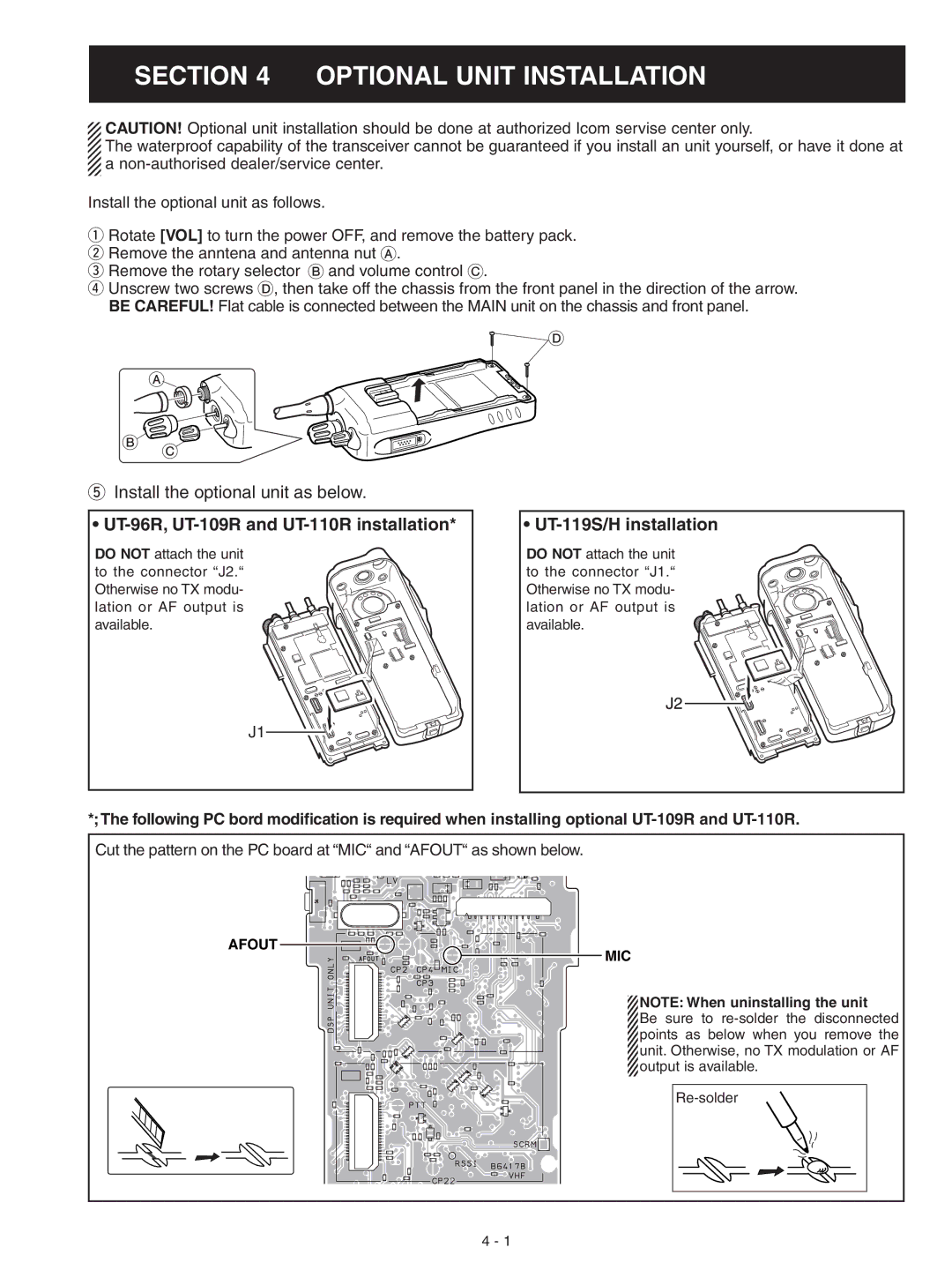
r Unscrew two screws D, then take off the chassis from the front panel in the direction of the arrow. BE CAREFUL! Flat cable is connected between the MAIN unit on the chassis and front panel.
D
A
B C
tInstall the optional unit as below.
• UT-96R, UT-109R and UT-110R installation*
DO NOT attach the unit to the connector “J2.“ Otherwise no TX modu- lation or AF output is available.
• UT-119S/H installation
DO NOT attach the unit to the connector “J1.“ Otherwise no TX modu- lation or AF output is available.
J1
*;The following PC bord modification is required when installing optional
Cut the pattern on the PC board at “MIC“ and “AFOUT“ as shown below.
AFOUT
MIC
NOTE: When uninstalling the unit
Be sure to
4 - 1