SECTION 3 DISASSEMBLY INSTRUCTIONS
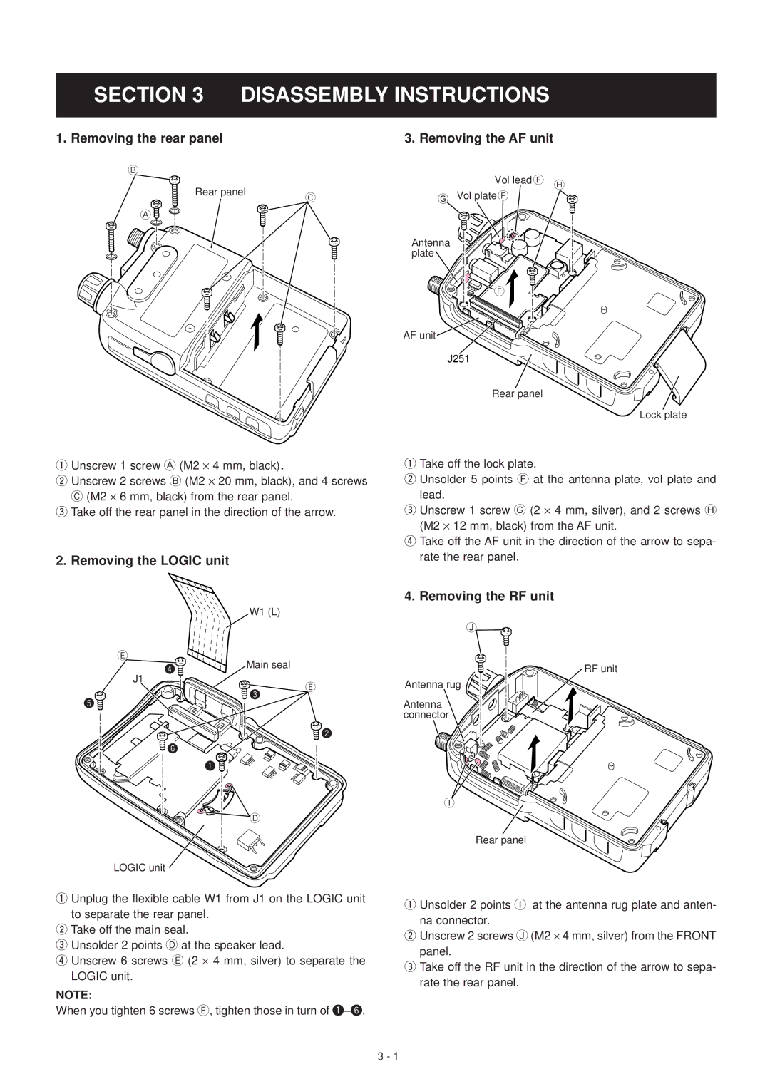
1. Removing the rear panel |
| 3. Removing the AF unit | |
B |
| Vol lead F H | |
Rear panel |
| ||
C | G Vol plate F | ||
| |||
A |
|
| |
|
| Antenna | |
|
| plate | |
|
| F |
AF unit
J251
Rear panel
Lock plate
qUnscrew 1 screw A (M2 ⋅ 4 mm, black).
wUnscrew 2 screws B (M2 ⋅ 20 mm, black), and 4 screws
C(M2 ⋅ 6 mm, black) from the rear panel.
eTake off the rear panel in the direction of the arrow.
2. Removing the LOGIC unit
| W1 (L) |
|
E | Main seal |
|
4 |
| |
|
| |
J1 |
| E |
| 3 | |
5 |
| |
|
|
qTake off the lock plate.
wUnsolder 5 points F at the antenna plate, vol plate and lead.
eUnscrew 1 screw G (2 ⋅ 4 mm, silver), and 2 screws H (M2 ⋅ 12 mm, black) from the AF unit.
rTake off the AF unit in the direction of the arrow to sepa- rate the rear panel.
4. Removing the RF unit
J
RF unit
Antenna rug
Antenna connector
![]() 6
6 ![]()
![]() 2
2
1![]()
D
LOGIC unit
qUnplug the flexible cable W1 from J1 on the LOGIC unit to separate the rear panel.
wTake off the main seal.
eUnsolder 2 points D at the speaker lead.
rUnscrew 6 screws E (2 ⋅ 4 mm, silver) to separate the LOGIC unit.
NOTE:
When you tighten 6 screws E, tighten those in turn of
I
Rear panel
qUnsolder 2 points I at the antenna rug plate and anten- na connector.
wUnscrew 2 screws J (M2 ⋅ 4 mm, silver) from the FRONT panel.
eTake off the RF unit in the direction of the arrow to sepa- rate the rear panel.
3 - 1