Before You Begin continued
1.3European installations
This Micro Motion product complies with all applicable European directives when properly installed in accordance with the instructions in this manual. Refer to the EC declaration of conformity for directives that apply to this product.
The EC declaration of conformity, with all applicable European directives, and the complete ATEX Installation Drawings and Instructions are available on the internet at www.micromotion.com/atex or through your local Micro Motion support center.
1.4Definitions
•The term “sensor” refers to a Micro Motion sensor only.
•The term “flowmeter” refers to an IFT9701 transmitter and a sensor installed as a flowmetering system.
1.5Flowmeter components
The IFT9701 transmitter can be integrally mounted to a Micro Motion
The IFT9701 transmitter does not operate with Micro Motion
•If the transmitter is integrally mounted to the sensor, the flowmeter includes the components shown in Figure
•If the transmitter will be remotely mounted from the sensor, the transmitter includes the components shown in Figure
The transmitter is available with an optional liquid crystal display (LCD), as shown in Figure
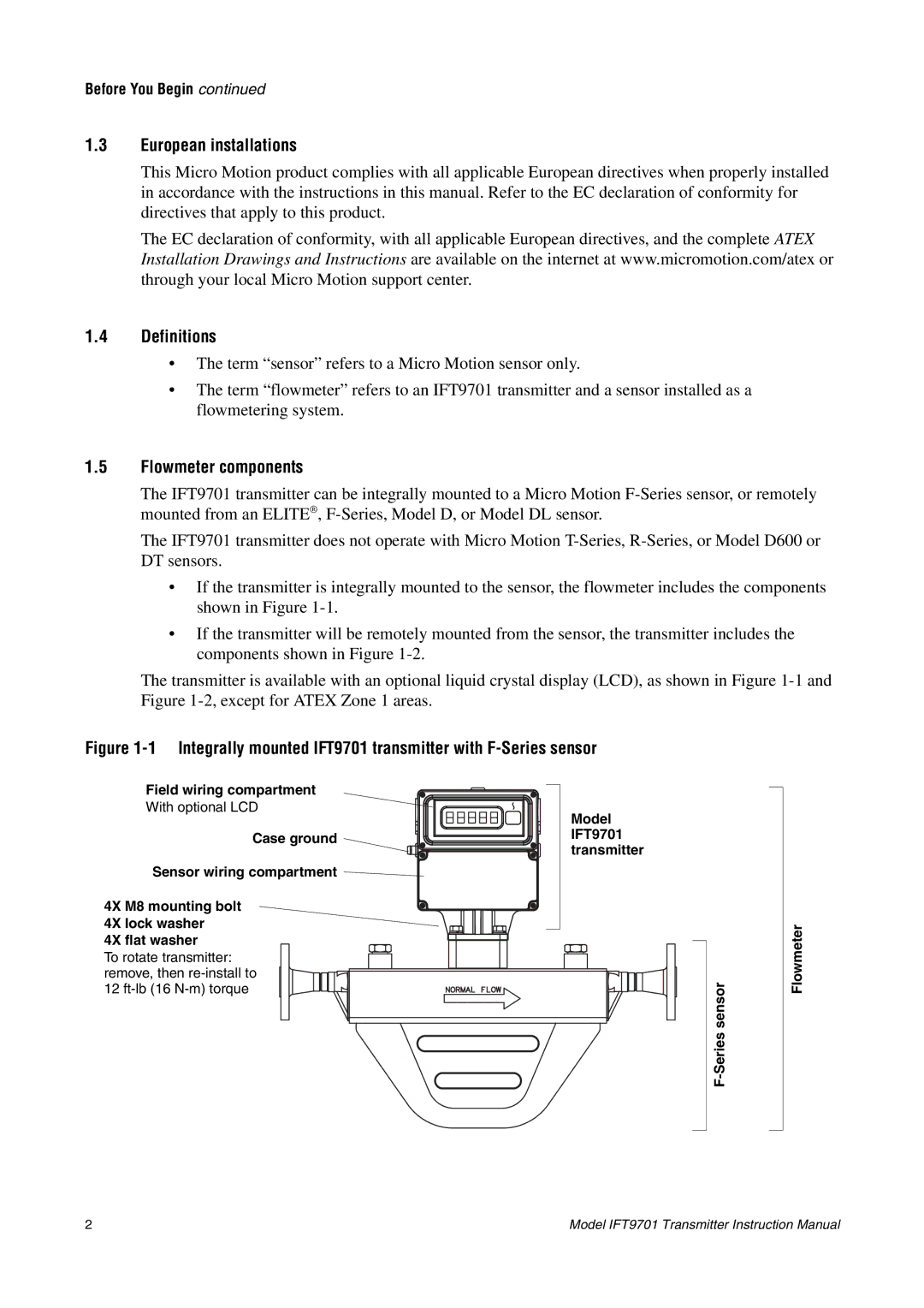
Figure 1-1 Integrally mounted IFT9701 transmitter with F-Series sensor
Field wiring compartment
With optional LCD
Case ground ![]()
Sensor wiring compartment ![]()
4X M8 mounting bolt
4X lock washer
4X flat washer
To rotate transmitter: remove, then
Model
IFT9701 transmitter
Flowmeter
2 | Model IFT9701 Transmitter Instruction Manual |