Configuration with a HART Communicator continued
6.Multiply the meter factor from Step 5 by the first five digits of the current flow calibration factor. This is the first five digits of the new flow calibration factor.
First 5 digits of new FloCal factor
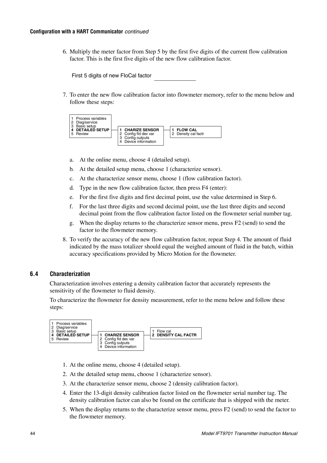
7.To enter the new flow calibration factor into flowmeter memory, refer to the menu below and follow these steps:
1Process variables
2Diag/service
3Basic setup
4DETAILED SETUP
5Review
1CHARIZE SENSOR
2Config fld dev var
3Config outputs
4Device information
1FLOW CAL
2Density cal factr
a.At the online menu, choose 4 (detailed setup).
b.At the detailed setup menu, choose 1 (characterize sensor).
c.At the characterize sensor menu, choose 1 (flow calibration factor).
d.Type in the new flow calibration factor, then press F4 (enter):
e.For the first five digits and first decimal point, use the value determined in Step 6.
f.For the last three digits and second decimal point, use the last three digits and second decimal point from the flow calibration factor listed on the flowmeter serial number tag.
g.When the display returns to the characterize sensor menu, press F2 (send) to send the factor to the flowmeter memory.
8.To verify the accuracy of the new flow calibration factor, repeat Step 4. The amount of fluid indicated by the mass totalizer should equal the weighed amount of fluid in the batch, within accuracy specifications provided by Micro Motion for the flowmeter.
6.4Characterization
Characterization involves entering a density calibration factor that accurately represents the sensitivity of the flowmeter to fluid density.
To characterize the flowmeter for density measurement, refer to the menu below and follow these steps:
1Process variables
2Diag/service
3Basic setup
4DETAILED SETUP
5Review
1CHARIZE SENSOR
2Config fld dev var
3Config outputs
4Device information
1Flow cal
2DENSITY CAL FACTR
1.At the online menu, choose 4 (detailed setup).
2.At the detailed setup menu, choose 1 (characterize sensor).
3.At the characterize sensor menu, choose 2 (density calibration factor).
4.Enter the
5.When the display returns to the characterize sensor menu, press F2 (send) to send the factor to the flowmeter memory.
44 | Model IFT9701 Transmitter Instruction Manual |