Flowmeter Startup continued
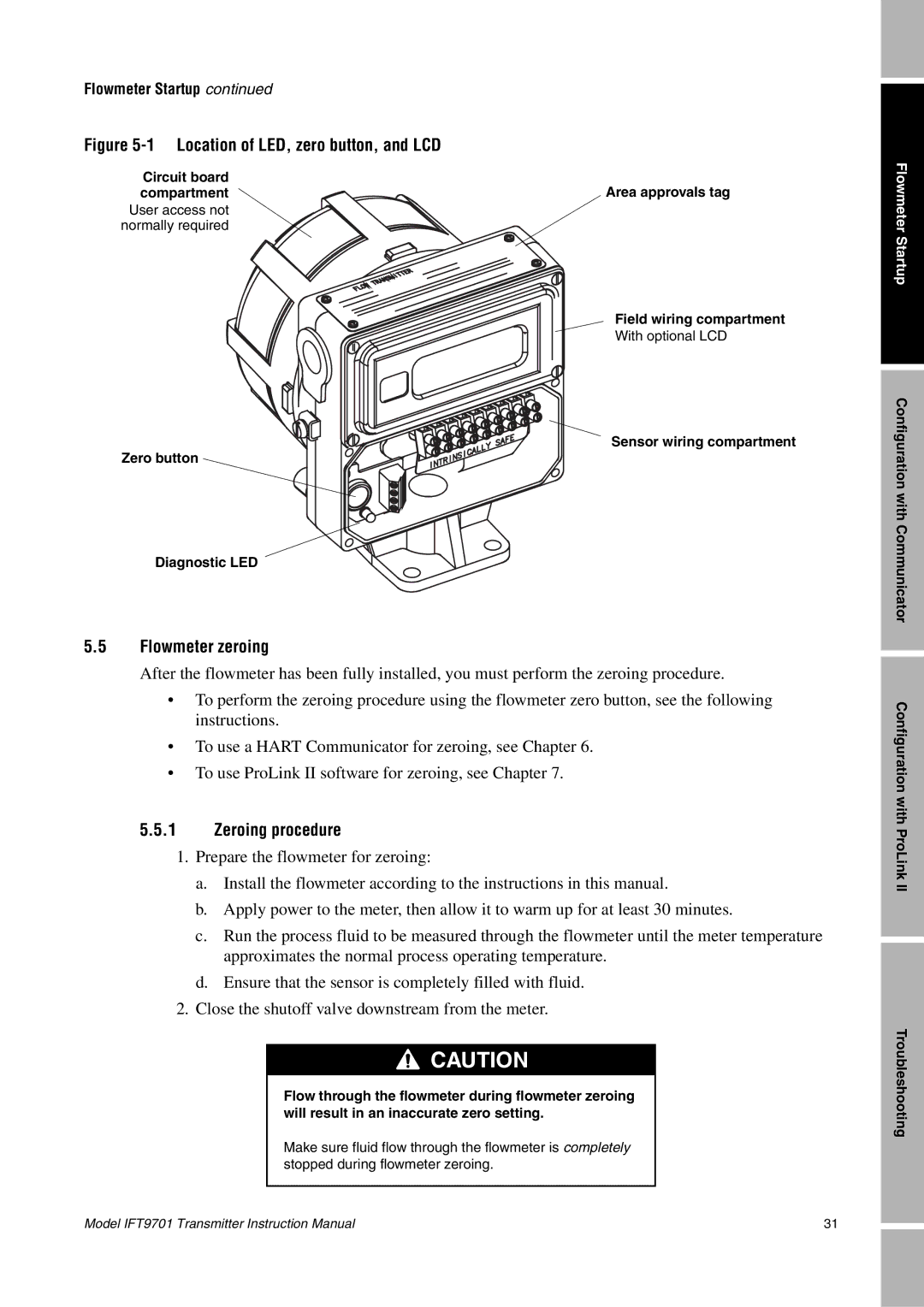
Figure 5-1 Location of LED, zero button, and LCD
Circuit board | Area approvals tag |
compartment | |
User access not |
|
normally required |
|
Field wiring compartment
With optional LCD
Sensor wiring compartment
Zero button
Diagnostic LED
5.5Flowmeter zeroing
After the flowmeter has been fully installed, you must perform the zeroing procedure.
•To perform the zeroing procedure using the flowmeter zero button, see the following instructions.
•To use a HART Communicator for zeroing, see Chapter 6.
•To use ProLink II software for zeroing, see Chapter 7.
5.5.1Zeroing procedure
1.Prepare the flowmeter for zeroing:
a.Install the flowmeter according to the instructions in this manual.
b.Apply power to the meter, then allow it to warm up for at least 30 minutes.
c.Run the process fluid to be measured through the flowmeter until the meter temperature approximates the normal process operating temperature.
d.Ensure that the sensor is completely filled with fluid.
2.Close the shutoff valve downstream from the meter.
![]()
![]()
![]() CAUTION
CAUTION
Flow through the flowmeter during flowmeter zeroing will result in an inaccurate zero setting.
Make sure fluid flow through the flowmeter is completely stopped during flowmeter zeroing.
Flowmeter Startup
Configuration with Communicator
Configuration with ProLink II
Troubleshooting
Model IFT9701 Transmitter Instruction Manual | 31 |