Configuration with ProLink II Software continued
To configure the pulse output:
1.From the ProLink menu, click on Configuration.
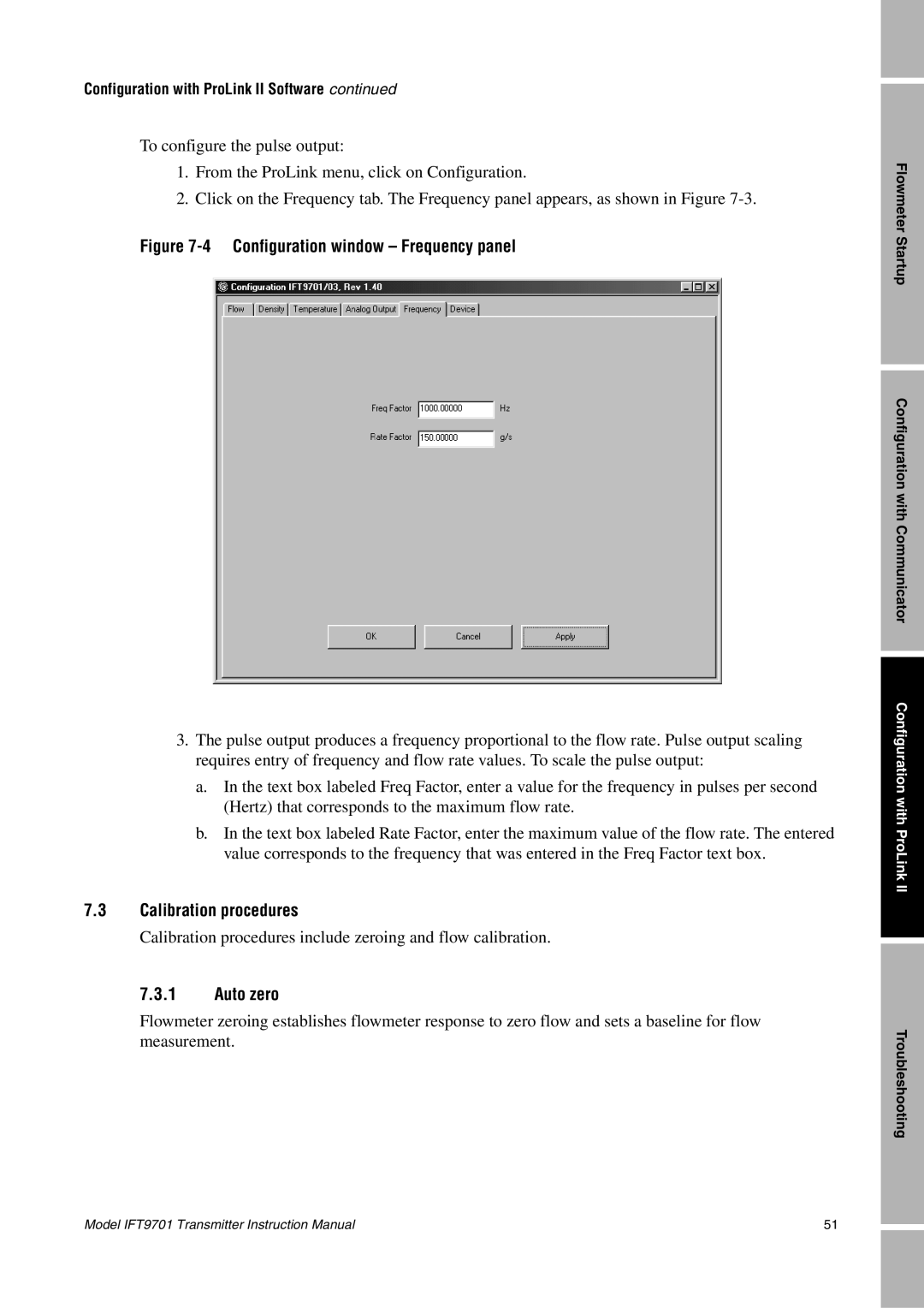
2.Click on the Frequency tab. The Frequency panel appears, as shown in Figure
Figure 7-4 Configuration window – Frequency panel
3.The pulse output produces a frequency proportional to the flow rate. Pulse output scaling requires entry of frequency and flow rate values. To scale the pulse output:
a.In the text box labeled Freq Factor, enter a value for the frequency in pulses per second (Hertz) that corresponds to the maximum flow rate.
b.In the text box labeled Rate Factor, enter the maximum value of the flow rate. The entered value corresponds to the frequency that was entered in the Freq Factor text box.
7.3Calibration procedures
Calibration procedures include zeroing and flow calibration.
7.3.1Auto zero
Flowmeter zeroing establishes flowmeter response to zero flow and sets a baseline for flow measurement.
Flowmeter Startup
Configuration with Communicator
Configuration with ProLink II
Troubleshooting
Model IFT9701 Transmitter Instruction Manual | 51 |