Power Supply and Output Wiring continued
4.4.2Milliamp output connected to Bell 202 multidrop network
Devices in a Bell 202 multidrop network communicate by sending and receiving signals to and from one another. HART protocol supports up to 15 transmitters in a Bell 202 multidrop network.
Other Rosemount SMART FAMILY transmitters can also participate in a
•A Bell 202 multidrop network uses
•A HART Communicator or other
Using multiple transmitters in a
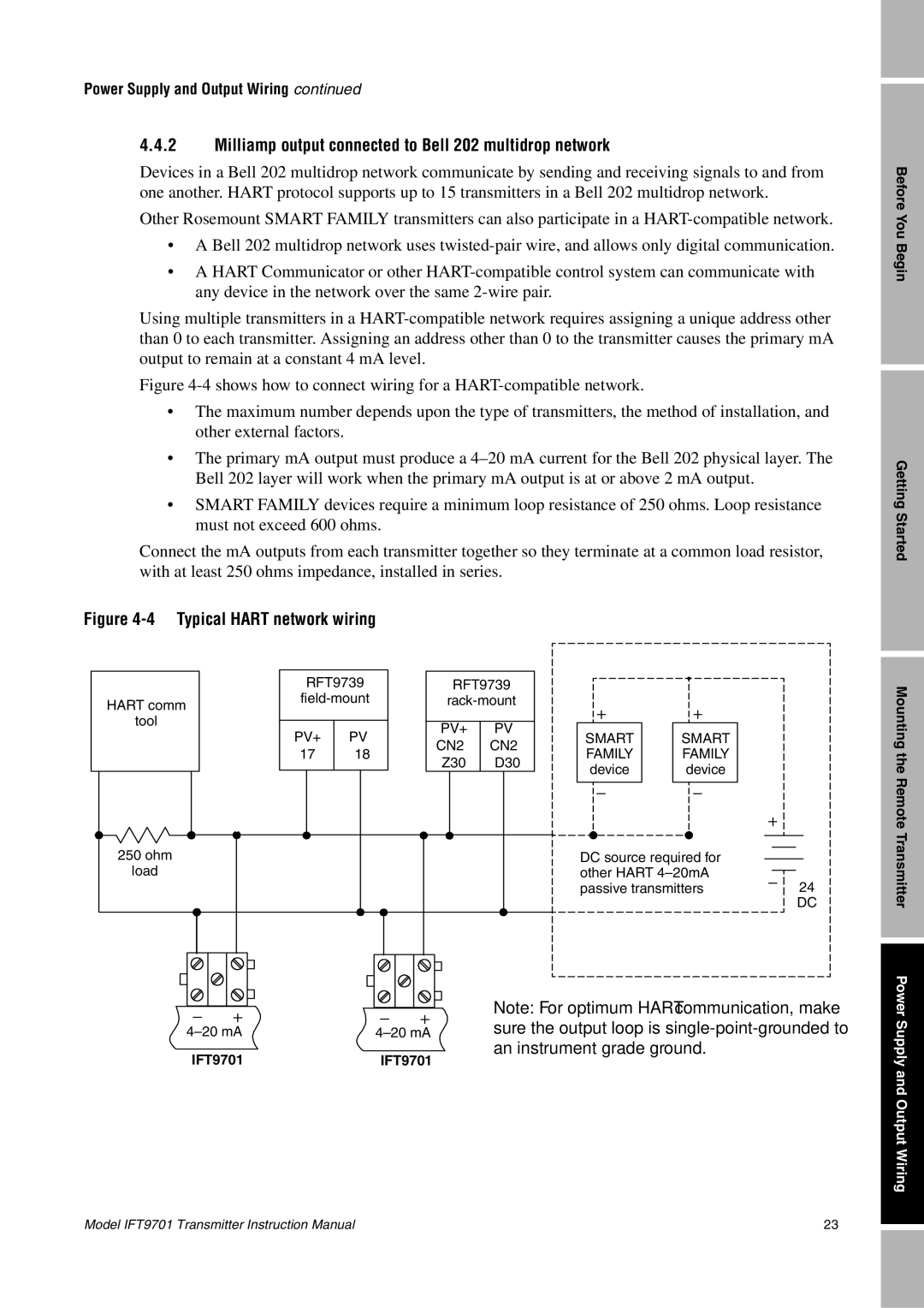
Figure 4-4 shows how to connect wiring for a HART-compatible network.
•The maximum number depends upon the type of transmitters, the method of installation, and other external factors.
•The primary mA output must produce a 4–20 mA current for the Bell 202 physical layer. The Bell 202 layer will work when the primary mA output is at or above 2 mA output.
•SMART FAMILY devices require a minimum loop resistance of 250 ohms. Loop resistance must not exceed 600 ohms.
Connect the mA outputs from each transmitter together so they terminate at a common load resistor, with at least 250 ohms impedance, installed in series.
Figure 4-4 Typical HART network wiring
Before You Begin
Getting Started
HART comm
tool
250ohm load
RFT9739
PV+ | PV− | ||||
17 | 18 |
| |||
|
|
|
|
|
|
|
|
|
|
|
|
|
|
|
|
|
|
RFT9739
| PV+ | PV− | |||
| CN2− | CN2− | |||
| Z30 | D30 | |||
|
|
|
|
|
|
|
|
|
|
|
|
|
|
|
|
|
|
SMART | SMART |
FAMILY | FAMILY |
device | device |
|
|
DC source required for other HART
24
DC
Mounting the Remote Transmitter
IFT9701
Note: For optimum HART communication, make
IFT9701
Power Supply and Output Wiring
Model IFT9701 Transmitter Instruction Manual | 23 |