Configuration with a HART Communicator continued
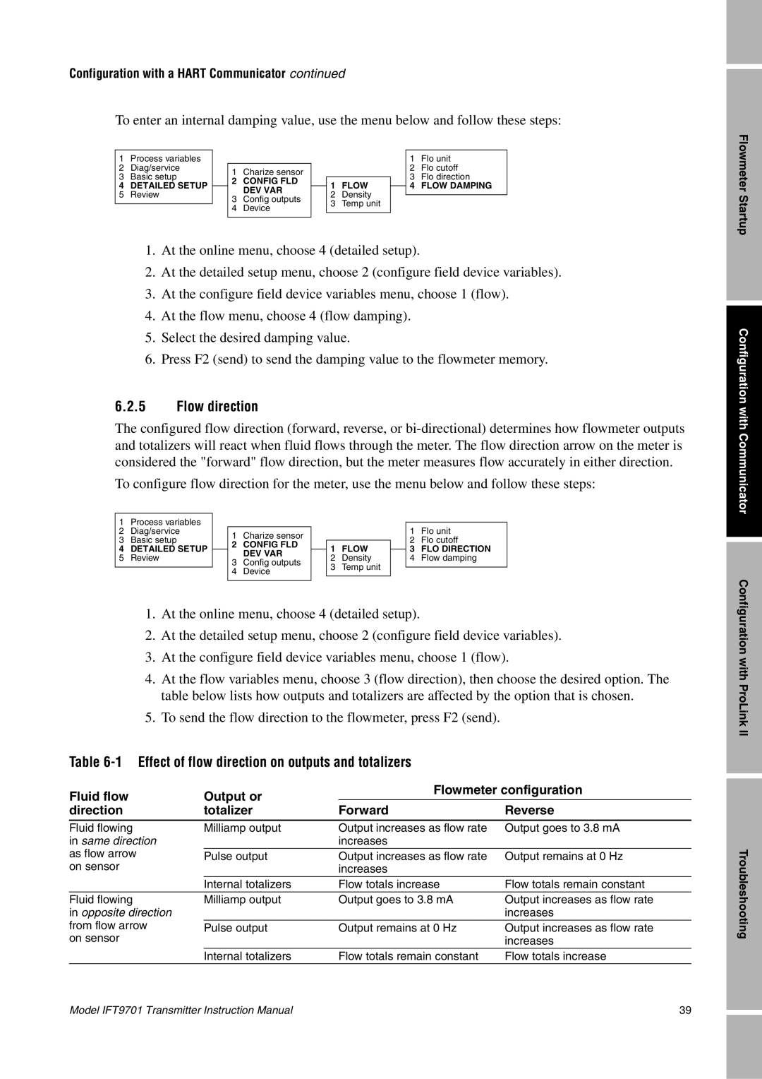
To enter an internal damping value, use the menu below and follow these steps:
1 | Process variables |
|
|
|
|
|
|
| 1 | Flo unit |
2 | Diag/service |
| 1 | Charize sensor |
|
|
|
| 2 | Flo cutoff |
3 | Basic setup |
|
|
|
|
| 3 | Flo direction | ||
4 | DETAILED SETUP |
| 2 | CONFIG FLD |
| 1 | FLOW |
| 4 | FLOW DAMPING |
|
| DEV VAR |
|
| ||||||
5 | Review |
|
|
| 2 | Density |
|
|
| |
| 3 | Config outputs |
|
|
|
| ||||
|
|
|
| 3 | Temp unit |
|
|
| ||
|
|
| 4 | Device |
|
|
|
| ||
|
|
|
|
|
|
|
|
| ||
|
|
|
|
|
|
|
|
|
|
|
1. At the online menu, choose 4 (detailed setup).
2. At the detailed setup menu, choose 2 (configure field device variables).
3. At the configure field device variables menu, choose 1 (flow).
4. At the flow menu, choose 4 (flow damping).
5. Select the desired damping value.
6. Press F2 (send) to send the damping value to the flowmeter memory.
6.2.5 Flow direction
The configured flow direction (forward, reverse, or
To configure flow direction for the meter, use the menu below and follow these steps:
1 | Process variables |
|
|
|
|
|
|
|
|
|
2 | Diag/service |
| 1 | Charize sensor |
|
|
|
| 1 | Flo unit |
3 | Basic setup |
|
|
|
|
| 2 | Flo cutoff | ||
4 | DETAILED SETUP |
| 2 | CONFIG FLD |
| 1 | FLOW |
| 3 | FLO DIRECTION |
|
| DEV VAR |
|
| ||||||
5 | Review |
|
|
| 2 | Density |
| 4 | Flow damping | |
| 3 | Config outputs |
|
| ||||||
|
|
|
| 3 | Temp unit |
|
|
| ||
|
|
| 4 | Device |
|
|
|
| ||
|
|
|
|
|
|
|
|
| ||
|
|
|
|
|
|
|
|
|
|
|
1. At the online menu, choose 4 (detailed setup).
2. At the detailed setup menu, choose 2 (configure field device variables).
3. At the configure field device variables menu, choose 1 (flow).
4. At the flow variables menu, choose 3 (flow direction), then choose the desired option. The table below lists how outputs and totalizers are affected by the option that is chosen.
5. To send the flow direction to the flowmeter, press F2 (send).
Table 6-1 Effect of flow direction on outputs and totalizers
Fluid flow | Output or | Flowmeter configuration | |
|
| ||
direction | totalizer | Forward | Reverse |
|
|
|
|
Fluid flowing | Milliamp output | Output increases as flow rate | Output goes to 3.8 mA |
in same direction |
| increases |
|
as flow arrow | Pulse output | Output increases as flow rate | Output remains at 0 Hz |
on sensor |
| increases |
|
| Internal totalizers | Flow totals increase | Flow totals remain constant |
Fluid flowing | Milliamp output | Output goes to 3.8 mA | Output increases as flow rate |
in opposite direction |
|
| increases |
from flow arrow | Pulse output | Output remains at 0 Hz | Output increases as flow rate |
on sensor |
|
| increases |
| Internal totalizers | Flow totals remain constant | Flow totals increase |
Flowmeter Startup
Configuration with Communicator
Configuration with ProLink II
Troubleshooting
Model IFT9701 Transmitter Instruction Manual | 39 |