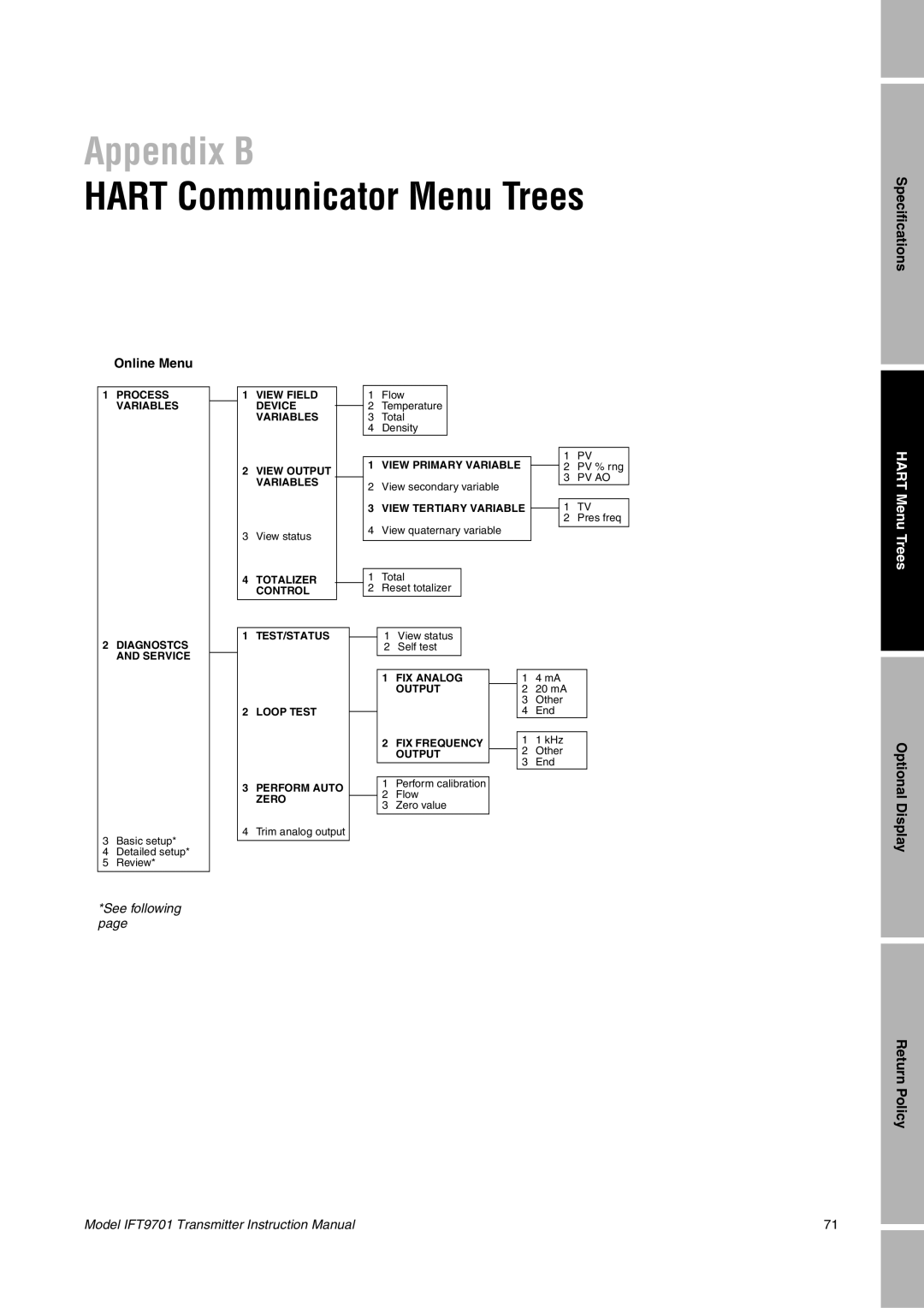
Appendix B
HART Communicator Menu Trees
Online Menu
1 | PROCESS |
| 1 | VIEW FIELD |
|
| 1 | Flow |
|
|
|
|
|
| |||||
| VARIABLES |
|
| DEVICE |
|
|
| 2 | Temperature |
|
|
|
|
|
| ||||
|
|
|
|
|
|
|
|
|
|
| |||||||||
|
|
|
| VARIABLES |
|
| 3 | Total |
|
|
|
|
|
| |||||
|
|
|
|
|
|
|
| 4 | Density |
|
|
|
|
|
| ||||
|
|
|
|
|
|
|
|
|
|
|
|
|
|
|
|
|
|
|
|
|
|
|
|
|
|
|
|
|
|
|
|
|
|
|
|
| 1 | PV | |
|
|
| 2 | VIEW OUTPUT |
|
|
| 1 | VIEW PRIMARY VARIABLE |
|
| 2 | PV % rng | ||||||
|
|
|
|
|
| ||||||||||||||
|
|
|
|
|
|
|
|
|
|
|
|
|
| 3 | PV AO | ||||
|
|
|
| VARIABLES |
|
| 2 | View secondary variable |
|
| |||||||||
|
|
|
|
|
|
|
|
|
|
| |||||||||
|
|
|
|
|
|
|
|
|
|
|
|
| |||||||
|
|
|
|
|
|
|
|
|
|
|
|
|
| ||||||
|
|
|
|
|
|
|
| 3 | VIEW TERTIARY VARIABLE |
| 1 | TV | |||||||
|
|
|
|
|
|
|
| ||||||||||||
|
|
|
|
|
|
|
|
|
|
|
|
|
|
|
|
| 2 | Pres freq | |
|
|
| 3 | View status |
|
| 4 | View quaternary variable |
|
|
|
|
| ||||||
|
|
|
|
|
|
|
|
|
| ||||||||||
|
|
|
|
|
|
|
|
|
|
|
|
|
|
|
|
| |||
|
|
|
|
|
|
|
|
|
|
|
|
|
|
|
| ||||
|
|
| 4 | TOTALIZER |
|
|
| 1 | Total |
|
|
|
|
|
| ||||
|
|
|
| CONTROL |
|
| 2 | Reset totalizer |
|
|
|
|
|
| |||||
|
|
|
|
|
|
|
|
|
|
|
|
|
|
|
|
|
|
|
|
|
|
|
|
|
|
|
|
|
|
|
|
|
|
|
| ||||
2 | DIAGNOSTCS |
| 1 | TEST/STATUS |
|
| 1 | View status |
|
|
|
|
|
| |||||
|
|
|
|
|
|
| |||||||||||||
|
|
|
|
|
|
| 2 | Self test |
|
|
|
|
|
| |||||
| AND SERVICE |
|
|
|
|
|
|
|
|
|
|
|
|
|
|
|
|
|
|
|
|
|
|
|
|
|
|
|
|
|
|
|
|
|
|
|
|
| |
|
|
|
|
|
|
|
|
|
|
|
|
|
|
|
|
|
| ||
|
|
|
|
|
|
|
|
| 1 | FIX ANALOG |
|
| 1 | 4 mA |
|
| |||
|
|
|
|
|
|
|
|
|
| OUTPUT |
|
| 2 | 20 mA |
|
| |||
|
|
|
|
|
|
|
|
|
|
|
|
|
|
| 3 | Other |
|
| |
|
|
| 2 | LOOP TEST |
|
|
|
|
|
|
|
| 4 | End |
|
| |||
|
|
|
|
|
|
|
|
|
|
|
| ||||||||
|
|
|
|
|
|
|
|
|
|
|
|
|
|
|
|
| |||
|
|
|
|
|
|
|
|
| 2 | FIX FREQUENCY |
|
| 1 | 1 kHz |
|
| |||
|
|
|
|
|
|
|
|
|
| OUTPUT |
|
| 2 | Other |
|
| |||
|
|
|
|
|
|
|
|
|
|
|
|
| |||||||
|
|
|
|
|
|
|
|
|
|
|
|
|
|
| 3 | End |
|
| |
|
|
|
|
|
|
|
|
|
|
|
|
|
|
|
|
| |||
|
|
|
|
|
|
|
|
|
|
|
|
|
|
|
|
|
|
|
|
|
|
| 3 | PERFORM AUTO |
|
| 1 | Perform calibration |
|
|
|
|
|
|
| ||||
|
|
|
|
| 2 | Flow |
|
|
|
|
|
|
| ||||||
|
|
|
| ZERO |
|
|
|
|
|
|
|
|
| ||||||
|
|
|
|
|
|
|
|
|
|
| |||||||||
|
|
|
|
|
| 3 | Zero value |
|
|
|
|
|
|
| |||||
|
|
|
|
|
|
|
|
|
|
|
|
|
|
|
| ||||
3 | Basic setup* |
| 4 | Trim analog output |
|
|
|
|
|
|
|
|
|
|
|
|
| ||
|
|
|
|
|
|
|
|
|
|
|
|
|
| ||||||
|
|
|
|
|
|
|
|
|
|
|
|
|
|
|
|
|
| ||
|
|
|
|
|
|
|
|
|
|
|
|
|
|
|
|
|
| ||
4 | Detailed setup* |
|
|
|
|
|
|
|
|
|
|
|
|
|
|
|
|
|
|
5 | Review* |
|
|
|
|
|
|
|
|
|
|
|
|
|
|
|
|
|
|
*See following page
Specifications
HART Menu Trees
Optional Display
Return Policy
Model IFT9701 Transmitter Instruction Manual | 71 |