Micro MotionTM
Micro Motion
Model IFT9701 Transmitter with Optional Display
P/N 3100572, Rev. E March
Page
Micro Motion
Model IFT9701 Transmitter with Optional Display
Page
Contents
Chapter 7 Configuration with ProLink II Software
Chapter 8 Troubleshooting
Chapter 6 Configuration with a HART Communicator
Contents continued
Page
Page
1.2Safety
Chapter
Before You Begin
1.1About this manual
1.5Flowmeter components
1.3European installations
1.4Definitions
Before You Begin continued
Power Supply and Output Wiring
Field wiring
Sensor wiring
Figure 1-2Remotely mounted IFT9701 transmitter
Page
Chapter
Getting Started
2.1Safety, reliability, accessibility
2.1.1Hazardous area
2.1.3Temperature, humidity, and vibration
Figure 2-1Location of approvals tag
2.1.2Orientation and mounting
2.2Transmitters approved for ATEX Zone
Power Supply and Output Wiring
2.1.4Visibility of tags
Explosion hazard
2.3Jumper settings
Figure 2-2Compartment tags and lockout device
Default settings
2.3.2Fault output levels
Figure 2-3Jumper location and settings
Optional settings
1.Screw the cover back onto the housing
3.1Overview
Remotely Mounting the Transmitter
Chapter
3.2Choosing the proper location
Remotely Mounting the Transmitter continued
Circuit board compartment
3.4Connecting the transmitter to the sensor
3.4.1Cable types
Figure 3-4Jacketed cable
High operating temperature limit
Table 3-1Temperature ranges for jacket material
Low operating temperature limit
Installation requirements
3.4.2Guidelines for conduit
3.4.4Wiring connections to sensor
Install drip legs in cable or conduit
3.4.3Guidelines for cable gland
Figure 3-7Cable connections to sensors
Wire color
Power Supply and Output Wiring
Table 3-3Sensor terminal designations
Sensor wiring terminals Sensor wiring compartment
Remotely Mounting the Transmitter continued
Chapter
Power Supply and Output Wiring
4.2Wiring guidelines
4.1Overview
4.3Connect power supply wiring
Figure 4-1Power supply wiring terminals
Power Supply and Output Wiring continued
Figure 4-2Output wiring terminals
Table 4-1Wire guidelines for DC power supply
4.4Connect output wiring
Power Supply and Output Wiring continued
4.4.1Milliamp output
Figure 4-3Milliamp output performance
Figure 4-4Typical HART network wiring
Note For optimum HART communication, make
Figure 4-5HART Communicator connections
4.4.4Pulse output
Pulse counter with pull-upto internal power Input
2Do not connect shields at this end
Page
5.3Startup procedures
Flowmeter Startup
5.2Customer service
Chapter
5.4.2Optional display
5.4.1Diagnostic LED
5.4Initialization
5.4.3Startup mode
5.5.1Zeroing procedure
Figure 5-1Location of LED, zero button, and LCD
5.5Flowmeter zeroing
5.5.2Diagnosing zero failure
5.7Process measurement
Configuration with Communicator
Configuration with ProLink Troubleshooting
Flowmeter Startup continued
Page
Configuration with a HART Communicator
6.1Configuration overview
Chapter
6.2Configuration parameters
6.2.1HART tag
6.2.2Measurement units
a. Whenever the display below appears, press F4 OK
6.2.3Flow cutoff
6.2.4Damping
6.2.5 Flow direction
6.2.6Range values for milliamp output
6.2.7Pulse output scaling
6.3Calibration procedures
6.3.1Auto zero
6.3.2Flow calibration procedure
Diagnosing zeroing failure
To calculate the flow calibration factor
6.4Characterization
Configuration with ProLink II Software
7.1Configuration overview
Chapter
7.2Configuration parameters
Figure 7-1Configuration window - Device panel
7.2.1HART tag
Figure 7-2Configuration window - Flow panel
7.2.2Process variable measurement
The pulse output goes to 0 Hz
Page
7.2.3Output configuration
Figure 7-4Configuration window - Frequency panel
7.3Calibration procedures
7.3.1Auto zero
To perform the auto zero procedure
7.3.2Flow calibration procedure
Figure 7-5Flow Calibration dialog box
Diagnosing zeroing failure
Figure 7-6Totalizer Control window
7.4Characterization
Figure 7-7Configuration window - Density panel
Configuration with ProLink II Software continued
8.3Transmitter diagnostic tools
Troubleshooting
8.1Customer service
8.3.1Diagnostic LED
8.3.2Optional LCD
8.3.3Fault outputs
Troubleshooting continued
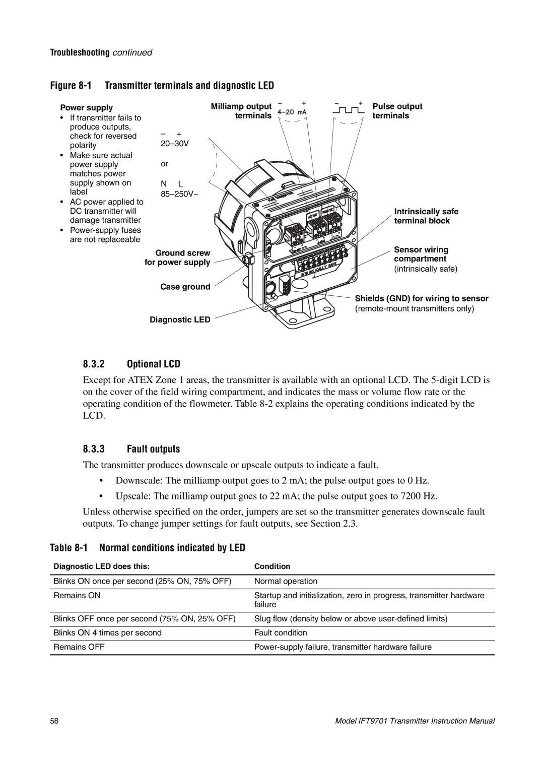
Table 8-1Normal conditions indicated by LED
8.4Power supply
Table 8-2Conditions indicated by optional LCD
Figure 8-2Power supply connections
8.5Wiring
Table 8-3Sensor terminal designations
8.6Over range and sensor failure conditions
8.7Slug flow
8.9Digital diagnostic messages
8.8Transmitter failure
Page
A.1 Performance specifications
IFT9701 Specifications
Appendix A
A.2 Functional specifications
A.2.8 Power supply options 85 to 250 VAC
A.2.6 Fault indication
A.2.7 Output testing Current source
A.2.2 Local display optional
A.3.2 Process fluid temperature limits
A.3 Environmental limits A.3.1 Temperature
See Process fluid vs. ambient temperature, below
5 to 95% non-condensing
IFT9701 Specifications continued
A.3.3 Humidity limits
A.3.4 Vibration limits
A.5 Environmental effects
A.6 Ambient temperature effect on milliamp output
A.7 Shipping weight
A.8 Hazardous area classifications
Page
Specifications
Appendix B
HART Communicator Menu Trees
HART Menu Trees
HART Communicator Menu Trees continued
Online Menu
See previous page
Installing the Optional Display
Appendix C
Installing the Optional Display continued
Back of Retaining clip display
D.1 General guidelines
Appendix D
Return Policy
D.2 New and unused equipment
Page
Index
Page
Page
Page
Page
Micro Motion Inc. USA
3100572
Micro MotionTM
Worldwide Headquarters