Getting Started continued
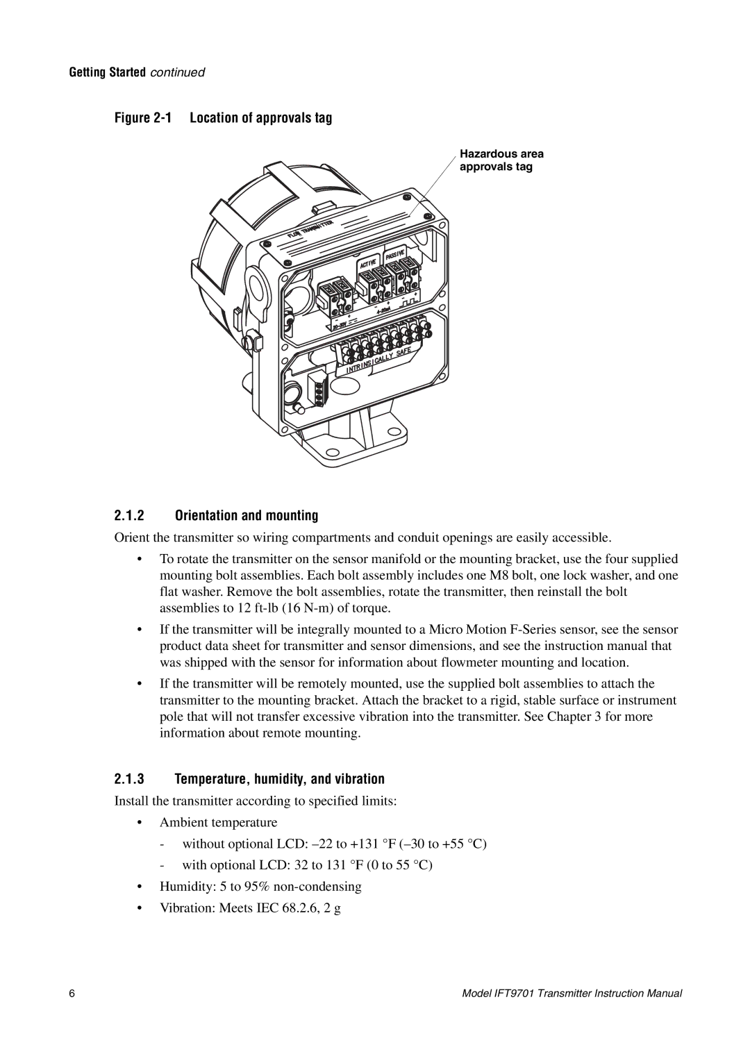
Figure 2-1 Location of approvals tag
Hazardous area approvals tag
2.1.2Orientation and mounting
Orient the transmitter so wiring compartments and conduit openings are easily accessible.
•To rotate the transmitter on the sensor manifold or the mounting bracket, use the four supplied mounting bolt assemblies. Each bolt assembly includes one M8 bolt, one lock washer, and one flat washer. Remove the bolt assemblies, rotate the transmitter, then reinstall the bolt assemblies to 12
•If the transmitter will be integrally mounted to a Micro Motion
•If the transmitter will be remotely mounted, use the supplied bolt assemblies to attach the transmitter to the mounting bracket. Attach the bracket to a rigid, stable surface or instrument pole that will not transfer excessive vibration into the transmitter. See Chapter 3 for more information about remote mounting.
2.1.3Temperature, humidity, and vibration
Install the transmitter according to specified limits:
•Ambient temperature
-without optional LCD:
-with optional LCD: 32 to 131 °F (0 to 55 °C)
•Humidity: 5 to 95%
•Vibration: Meets IEC 68.2.6, 2 g
6 | Model IFT9701 Transmitter Instruction Manual |