Configuration with ProLink II Software continued
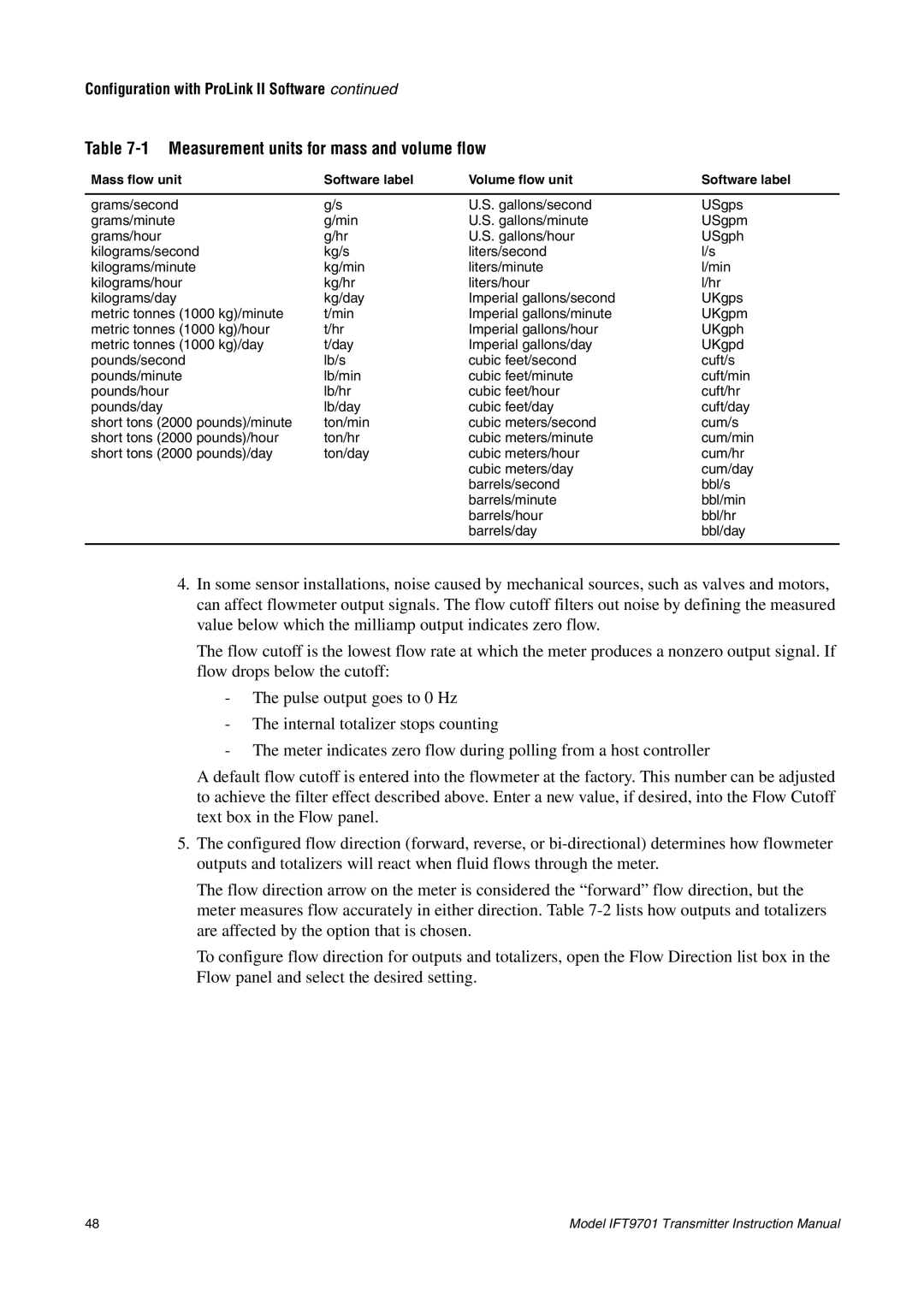
Table 7-1 Measurement units for mass and volume flow
Mass flow unit | Software label | Volume flow unit | Software label |
|
|
|
|
grams/second | g/s | U.S. gallons/second | USgps |
grams/minute | g/min | U.S. gallons/minute | USgpm |
grams/hour | g/hr | U.S. gallons/hour | USgph |
kilograms/second | kg/s | liters/second | l/s |
kilograms/minute | kg/min | liters/minute | l/min |
kilograms/hour | kg/hr | liters/hour | l/hr |
kilograms/day | kg/day | Imperial gallons/second | UKgps |
metric tonnes (1000 kg)/minute | t/min | Imperial gallons/minute | UKgpm |
metric tonnes (1000 kg)/hour | t/hr | Imperial gallons/hour | UKgph |
metric tonnes (1000 kg)/day | t/day | Imperial gallons/day | UKgpd |
pounds/second | lb/s | cubic feet/second | cuft/s |
pounds/minute | lb/min | cubic feet/minute | cuft/min |
pounds/hour | lb/hr | cubic feet/hour | cuft/hr |
pounds/day | lb/day | cubic feet/day | cuft/day |
short tons (2000 pounds)/minute | ton/min | cubic meters/second | cum/s |
short tons (2000 pounds)/hour | ton/hr | cubic meters/minute | cum/min |
short tons (2000 pounds)/day | ton/day | cubic meters/hour | cum/hr |
|
| cubic meters/day | cum/day |
|
| barrels/second | bbl/s |
|
| barrels/minute | bbl/min |
|
| barrels/hour | bbl/hr |
|
| barrels/day | bbl/day |
|
|
|
|
4.In some sensor installations, noise caused by mechanical sources, such as valves and motors, can affect flowmeter output signals. The flow cutoff filters out noise by defining the measured value below which the milliamp output indicates zero flow.
The flow cutoff is the lowest flow rate at which the meter produces a nonzero output signal. If flow drops below the cutoff:
-The pulse output goes to 0 Hz
-The internal totalizer stops counting
-The meter indicates zero flow during polling from a host controller
A default flow cutoff is entered into the flowmeter at the factory. This number can be adjusted to achieve the filter effect described above. Enter a new value, if desired, into the Flow Cutoff text box in the Flow panel.
5.The configured flow direction (forward, reverse, or
The flow direction arrow on the meter is considered the “forward” flow direction, but the meter measures flow accurately in either direction. Table
To configure flow direction for outputs and totalizers, open the Flow Direction list box in the Flow panel and select the desired setting.
48 | Model IFT9701 Transmitter Instruction Manual |