Configuration with a HART Communicator continued
6.2Configuration parameters
Use the basic setup menu to perform the following tasks:
•Assigning a HART tag to the flowmeter
•Changing measurement units for the mass or volume flow rate
•Setting range values for the milliamp output
•Scaling the pulse output
Use the detailed setup menu to perform the following tasks:
•Changing measurement units for density or temperature
•Changing the flow cutoff value
•Changing the internal damping value
•Changing the flow direction parameter
6.2.1HART tag
The HART tag consists of up to eight characters that identify the flowmeter when it communicates with other devices in a HART multidrop network.
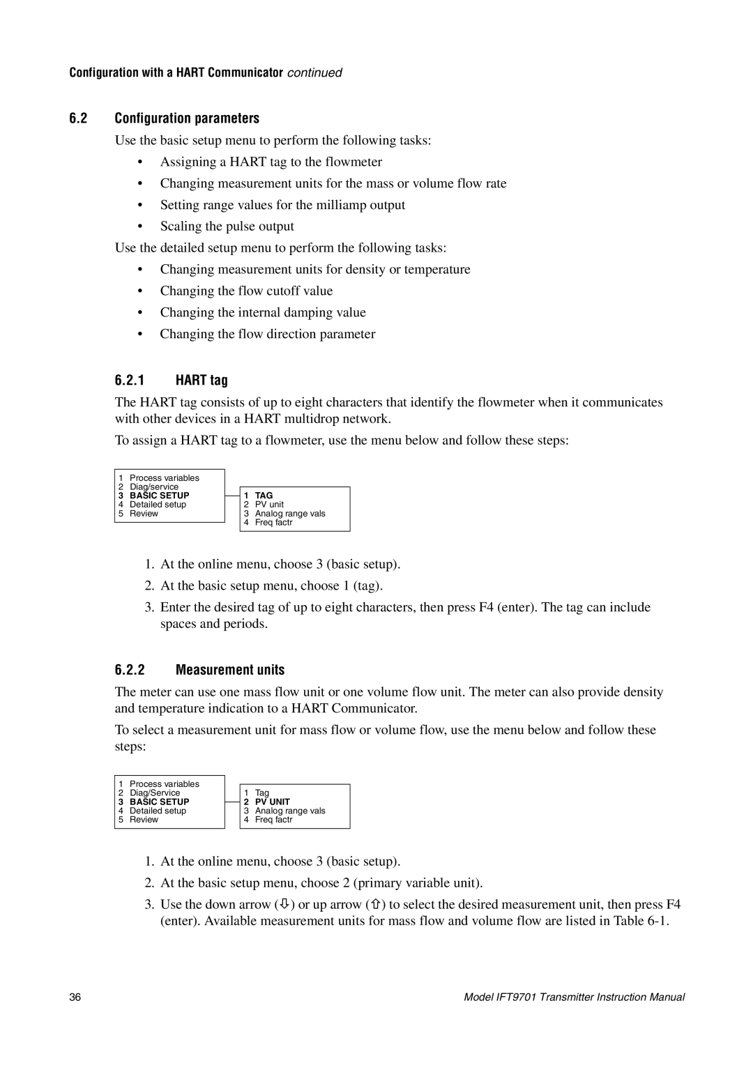
To assign a HART tag to a flowmeter, use the menu below and follow these steps:
1Process variables
2Diag/service
3BASIC SETUP
4Detailed setup
5Review
1TAG
2PV unit
3Analog range vals
4Freq factr
1.At the online menu, choose 3 (basic setup).
2.At the basic setup menu, choose 1 (tag).
3.Enter the desired tag of up to eight characters, then press F4 (enter). The tag can include spaces and periods.
6.2.2Measurement units
The meter can use one mass flow unit or one volume flow unit. The meter can also provide density and temperature indication to a HART Communicator.
To select a measurement unit for mass flow or volume flow, use the menu below and follow these steps:
1Process variables
2Diag/Service
3BASIC SETUP
4Detailed setup
5Review
1Tag
2PV UNIT
3Analog range vals
4Freq factr
1.At the online menu, choose 3 (basic setup).
2.At the basic setup menu, choose 2 (primary variable unit).
3.Use the down arrow (Ø) or up arrow (×) to select the desired measurement unit, then press F4 (enter). Available measurement units for mass flow and volume flow are listed in Table
36 | Model IFT9701 Transmitter Instruction Manual |