Appendix C
Installing the Optional Display
![]()
![]()
![]() WARNING
WARNING
Line voltage can cause electric shock or transmitter damage.
Disconnect input power before installing display.
To install the optional display, follow these steps:
1.Make sure you are wearing an
2.Disconnect input power to the flowmeter.
3.Loosen the captive screws that hold the field wiring compartment cover in place, then remove the cover.
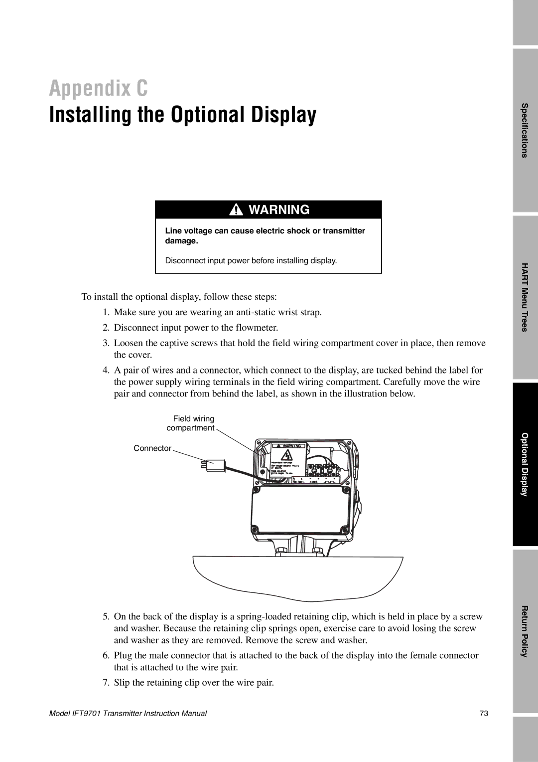
4.A pair of wires and a connector, which connect to the display, are tucked behind the label for the power supply wiring terminals in the field wiring compartment. Carefully move the wire pair and connector from behind the label, as shown in the illustration below.
Field wiring compartment ![]()
Connector ![]()
5.On the back of the display is a
6.Plug the male connector that is attached to the back of the display into the female connector that is attached to the wire pair.
7.Slip the retaining clip over the wire pair.
Specifications
HART Menu Trees
Optional Display
Return Policy
Model IFT9701 Transmitter Instruction Manual | 73 |